4
Manual No. 016-0230-044 Rev. F
35
POWERGLIDE PLUS
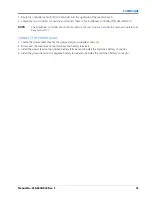
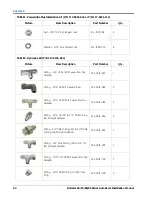
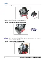
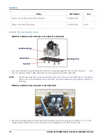
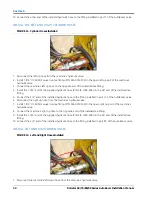
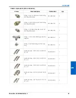
2. Install a 9/16” JIC M/M/F swivel run tee fitting (P/N 333-0012-043) in the left down port of the machine’s
hydraulic valve.
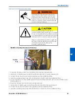
3. Connect the machine’s down hose to the opposite end of the installed tee fitting.
4. Install the supplied hydraulic hose (P/N 214-1000-229) to the remaining branch of the installed tee fitting.
5. Connect the other end of the installed hydraulic hose to the fitting installed in port LF CYL RTN of the
AutoBoom valve.
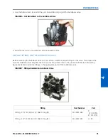
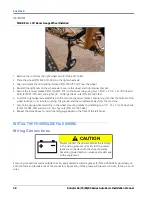
6. Disconnect the machine’s right down hose from the machine’s hydraulic valve.
7. Install a 9/16” JIC M/M/F swivel run tee fitting (P/N 333-0012-043) in the right down port of the machine’s
hydraulic valve.
8. Connect the machine’s down hose to the opposite end of the installed tee fitting.
9. Install the supplied hydraulic hose (P/N 214-1000-233) to the remaining branch of the installed tee fitting.
10. Connect other end of the installed hydraulic hose to the fitting installed in port RT CYL RTN of the AutoBoom
valve.
Summary of Contents for RoGator 64 Series
Page 9: ...2 Manual No 016 0230 044 Rev F 5 INTRODUCTION ...
Page 10: ...CHAPTER 2 6 RoGator 64 74 86 SS Series AutoBoom Installation Manual ...
Page 21: ...3 Manual No 016 0230 044 Rev F 17 POWERGLIDE POWERGLIDE HYDRAULIC SCHEMATIC ...
Page 48: ...CHAPTER 4 44 RoGator 64 74 86 SS Series AutoBoom Installation Manual GEN II CABLING ...
Page 61: ...5 Manual No 016 0230 044 Rev F 57 ULTRAGLIDE ULTRAGLIDE HYDRAULIC SCHEMATIC ...
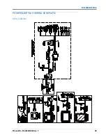
Page 71: ...Manual No 016 0230 044 Rev F 67 ULTRAGLIDE ULTRAGLIDE WIRING SCHEMATIC GEN I CABLING ...
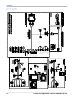
Page 72: ...CHAPTER 5 68 RoGator 64 74 86 SS Series AutoBoom Installation Manual GEN II CABLING ...
Page 75: ...6 Manual No 016 0230 044 Rev F 71 REPLACEMENT PARTS SENSORS ...
Page 76: ...CHAPTER 6 72 RoGator 64 74 86 SS Series AutoBoom Installation Manual ...

