C
HAPTER
4
28
RoGator 64/74/86/SS Series AutoBoom Installation Manual
INSTALL THE POWERGLIDE PLUS HYDRAULIC SYSTEM
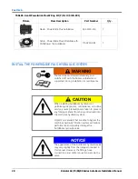
TABLE 6. Gen II PowerGlide Plus Wiring Kit (P/N 117-5130-001)
Picture
Item Description
Part Number
Qty.
Node - PowerGlide Plus AutoBoom
063-0130-010
1
Cable - PowerGlide Plus/UltraGlide with
CAN/Power Tee AutoBoom
115-0230-085
1
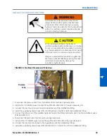
WARNING
The machine must remain stationary and
switched off, with the booms unfolded and
supported, during installation or maintenance.
CAUTION
When installing AutoBoom hydraulics or
performing diagnostics, maintenance, or routine
service, ensure precautions are taken to prevent
any foreign material from being introduced into
the machine’s hydraulic system.
Objects or materials that are able to bypass the
machine’s hydraulic filtration system will reduce
performance and possibly damage the
AutoBoom hydraulic valve.
NOTICE
The appearance of the AutoBoom hydraulic valve
may vary slightly from the images contained in
this manual. However, the fittings, hose
connections, and cable connections remain the
same.
Summary of Contents for RoGator 64 Series
Page 9: ...2 Manual No 016 0230 044 Rev F 5 INTRODUCTION ...
Page 10: ...CHAPTER 2 6 RoGator 64 74 86 SS Series AutoBoom Installation Manual ...
Page 21: ...3 Manual No 016 0230 044 Rev F 17 POWERGLIDE POWERGLIDE HYDRAULIC SCHEMATIC ...
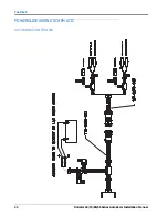
Page 48: ...CHAPTER 4 44 RoGator 64 74 86 SS Series AutoBoom Installation Manual GEN II CABLING ...
Page 61: ...5 Manual No 016 0230 044 Rev F 57 ULTRAGLIDE ULTRAGLIDE HYDRAULIC SCHEMATIC ...
Page 71: ...Manual No 016 0230 044 Rev F 67 ULTRAGLIDE ULTRAGLIDE WIRING SCHEMATIC GEN I CABLING ...
Page 72: ...CHAPTER 5 68 RoGator 64 74 86 SS Series AutoBoom Installation Manual GEN II CABLING ...
Page 75: ...6 Manual No 016 0230 044 Rev F 71 REPLACEMENT PARTS SENSORS ...
Page 76: ...CHAPTER 6 72 RoGator 64 74 86 SS Series AutoBoom Installation Manual ...


