


C
HAPTER
4
38
RoGator 64/74/86/SS Series AutoBoom Installation Manual
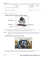
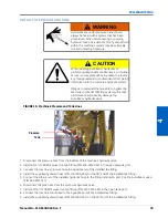
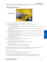
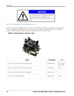
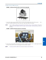
120’ BOOM
FIGURE 14. 120’ Boom Gauge Wheel Installed
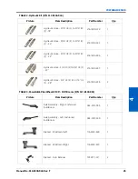
1. Remove the nuts from the right wheel axle (P/N 063-0131-585).
2. Place the wheel (P/N 322-0131-003) on the right wheel axle.
3. Align and place the hub retainer bracket (P/N 107-0171-617) over the wheel.
4. Reinstall the light nuts on the wheel axle to secure the wheel and hub retainer bracket.
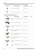
5. Secure the receiver bracket (P/N 116-0159-707) to the boom tube using four 1-9/16” x 2-1/2” L x 3/8” thread U-
bolts (P/N 107-0171-611) and eight 3/8” - 16 flanged lock nuts (P/N 312-1001-164).
6. Insert the right wheel axle assembly into the mounting receiver bracket, positioning it so that the bottom of the
wheel touches, or is close to touching, the ground and the wheel faces away from the machine.
7. Secure the gauge wheel assembly in the wheel mounting bracket by installing two 1/2” - 13 x 1-1/2 SS hex bolts
(P/N 311-0058-186) and two 1/2” zinc hex nuts (P/N 312-1001-043).
8. Repeat the steps above to install the left gauge wheel on the front of the left boom.
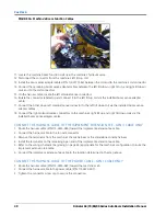
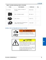
INSTALL THE POWERGLIDE PLUS WIRING
Wiring Connections
For wiring connections made outside the cab, apply dielectric silicone grease (P/N 222-0000-006) generously on
both the male and female ends of the connectors. Application of the grease will prevent corrosion to the pins and
wires.
CAUTION
Always connect the power cable as the last step
in the wiring process and verify that the power
leads are connected with the correct polarity.
Reversing power leads can cause severe damage
to the equipment.
Summary of Contents for RoGator 64 Series
Page 9: ...2 Manual No 016 0230 044 Rev F 5 INTRODUCTION ...
Page 10: ...CHAPTER 2 6 RoGator 64 74 86 SS Series AutoBoom Installation Manual ...
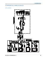
Page 21: ...3 Manual No 016 0230 044 Rev F 17 POWERGLIDE POWERGLIDE HYDRAULIC SCHEMATIC ...
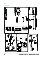
Page 48: ...CHAPTER 4 44 RoGator 64 74 86 SS Series AutoBoom Installation Manual GEN II CABLING ...
Page 61: ...5 Manual No 016 0230 044 Rev F 57 ULTRAGLIDE ULTRAGLIDE HYDRAULIC SCHEMATIC ...
Page 71: ...Manual No 016 0230 044 Rev F 67 ULTRAGLIDE ULTRAGLIDE WIRING SCHEMATIC GEN I CABLING ...
Page 72: ...CHAPTER 5 68 RoGator 64 74 86 SS Series AutoBoom Installation Manual GEN II CABLING ...
Page 75: ...6 Manual No 016 0230 044 Rev F 71 REPLACEMENT PARTS SENSORS ...
Page 76: ...CHAPTER 6 72 RoGator 64 74 86 SS Series AutoBoom Installation Manual ...