P/N 016-0171-675 Rev. A
25
INSTALLATION
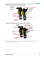
FIGURE 33. Low Flow
FIGURE 34. High Flow
2. Assemble the mixer injection point plumbing as shown below.
To Boom
Plumbing
M220 Clamp
and Gasket
M220 to M300
Reducer Coupler
M300 Clamps
and Gaskets
M300 Sweep
Elbow
4” Mixer with
Check Valve
M300 Sweep
Elbow with
Gauge Port
M300 Clamps
and Gaskets
M220 Clamp
and Gasket
M300 Sweep
Elbow
M220 to 2”
Hose Barb
M220 to 2”
Hose Barb
Injection Point
with Plumbing
Installed
To Hose
From
Machine
M300 Clamps
and Gaskets
M300 Sweep
Elbow
4” Mixer with
Check Valve
M300 Sweep
Elbow with
Gauge Port
M300 Clamps
and Gaskets
M300 Sweep
Elbow
Injection Point
with Plumbing
Installed
M300 to 3”
Hose Barb
M300 to 3”
Hose Barb
To Boom
Plumbing
To Hose
from Front
of Machine
Summary of Contents for ICD Sidekick Pro
Page 48: ...CHAPTER 5 44 ICD Sidekick Pro Injection for Case Trident Installation Manual ...
Page 57: ...P N 016 0171 675 Rev A 53 SYSTEM DIAGRAMS ...
Page 58: ...CHAPTER 6 54 ICD Sidekick Pro Injection for Case Trident Installation Manual ...
Page 60: ...INDEX 56 ICD Sidekick Pro Injection for Case Trident Installation Manual ...


