C
HAPTER
3
26
ICD Sidekick Pro Injection for Case Trident Installation Manual
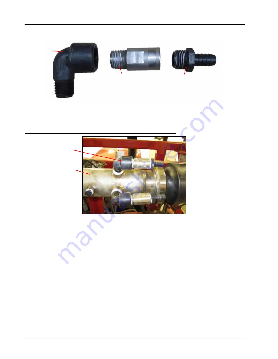
FIGURE 35.
Mixer Injection Point Plumbing Assembly
3. Seal the plumbing assembly threaded joints with the provided thread sealant.
4. Remove one of the existing 1/2” plugs at the inlet of the mixer assembly.
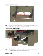
FIGURE 36.
Injection Point Plumbing Assembly Installed (Dual Pump Injection Point Shown)
5. Thread the injection point plumbing into the mixer.
6. Install the mixer to the upper center boom section of the machine with the supplied 3/8”-16 x 2-1/2” (for 120’)
or 1-5/16” U-bolts (for 90’ - 100’), 3/8” washers, 3/8” spacers (for 120’), and 3/8” nyloc nuts. Place the mixer so
that the inlet check valve is on the right side of the machine.
1/2” NPT
Street
Elbow
Injection Point
Check Valve
1/2” NPT to 1/2”
Hose Barb Fitting
Mixer
Assembly
Injection Point
Plumbing
Assembly
Summary of Contents for ICD Sidekick Pro
Page 48: ...CHAPTER 5 44 ICD Sidekick Pro Injection for Case Trident Installation Manual ...
Page 57: ...P N 016 0171 675 Rev A 53 SYSTEM DIAGRAMS ...
Page 58: ...CHAPTER 6 54 ICD Sidekick Pro Injection for Case Trident Installation Manual ...
Page 60: ...INDEX 56 ICD Sidekick Pro Injection for Case Trident Installation Manual ...


