background image

3 5

9.

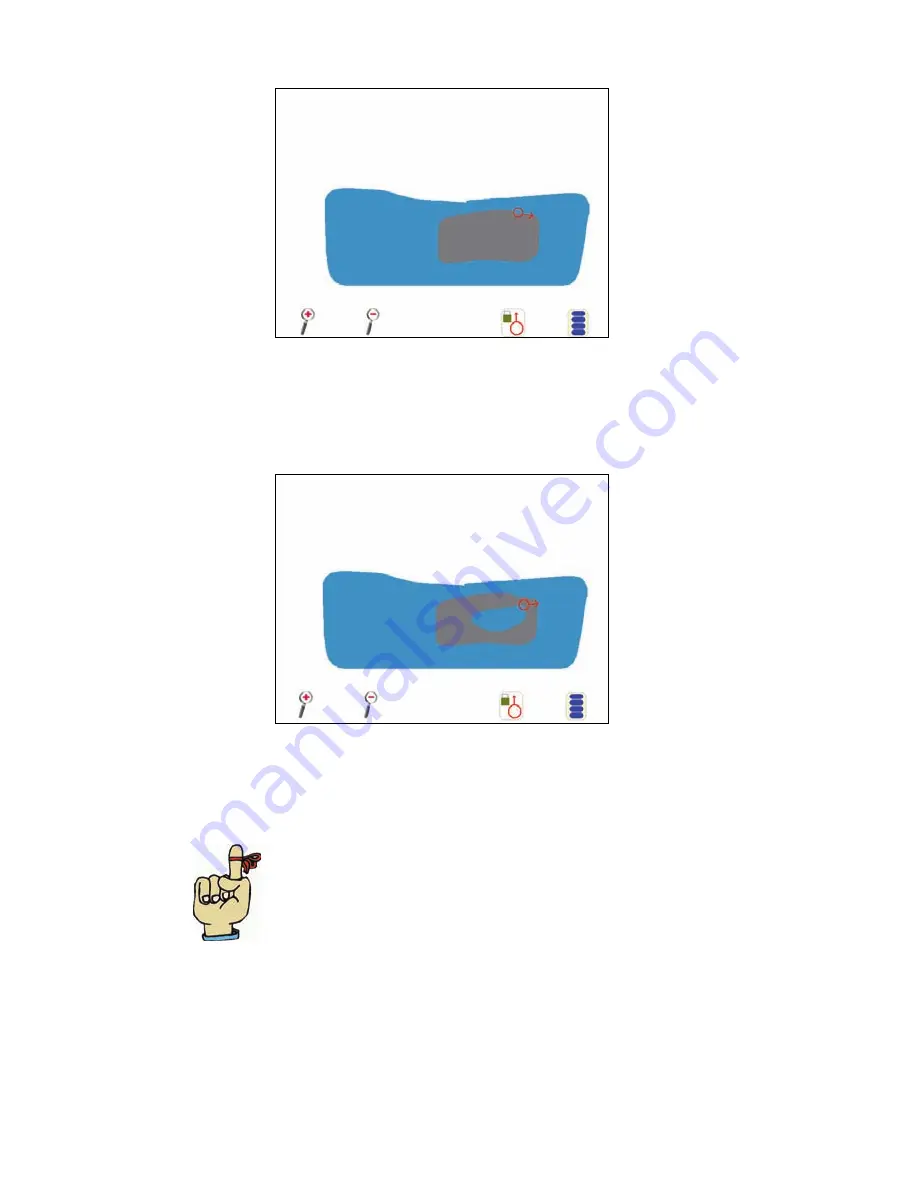
The no-spray zone will appear on the screen, along with the field 
boundary.

10. Press the 

Menu

 button and select 

Record Spray Zone

11. Select the Recording Reference Point and press 

OK

12. Begin recording the spray zone. When you are finished, press the 

Menu


button and select 

End Recording

. The spray zone will appear on the 

screen, along with the field boundary.

13. Press the 

Menu

 button and select 

Save and Exit

 to save and close the 

map.  

Helpful Hint:


After saving, a 3 boom width No Spray 

Zone will be added around the boundary.

Summary of Contents for ENVIZIO PLUS

Page 1: ...ENVIZIO PLUS Installation and Operation Manual ...

Page 2: ...eady for use You will not be prompted again for these two settings only the very first time you power on the system After that if you wish to change these settings you may do so via the Configuration Pages which you will learn about later in this manual Starting the Envizio Plus System 1 Press the Power switch to power on the Envizio Plus system 2 The first initial start up screen Swath Width disp...

Page 3: ... have set the desired number touch OK 4 The Home Screen will display and you can begin guidance Helpful Hints Normally the antenna position is set in reference to the application location If you touch Cancel on either of the two configuration screens above you will be prompted again to set these the next time you power on the Envizio Plus system This is the overall boom width for guidance To confi...

Page 4: ...reen name and time Note The time is only available if the Envizio Plus system is receiving RMC or ZDA NMEA messages 5 Job Status Shows the current status of the job as well as the job name that is displayed if a job is started 6 Start Guidance Starts any new job Touch the Start Guidance button to start a new job 7 Open Old Job Opens a previous or existing job Touch the Open Old Job button to view ...

Page 5: ...enabled and all operating conditions are met Yellow Caution This part of the system is receiving a warning Operation can proceed with caution Touch this icon to view the system warning Red X The system is experiencing a problem in this area or the user has elected to not use this function This problem may need to be corrected before proceeding with operation Touch this icon to view the system prob...

Page 6: ...ine Green indicates that the booms are on and coverage is being logged A B Line Speed Course or Rates if using a Switch to this guidance pattern Over Ground COG Guidance Line Distance To Line Raven console touch to toggle Touch to enable the AccuBoom override if using a CAN system ...

Page 7: ...e icon Pivot Pattern Allows you to switch to the Pivot pattern from the pattern you are presently running by touching the icon Zoom Out Allows you to zoom out from the field or area by touching the icon Zoom In Allows you to zoom in on the field or area by touching the icon Boom Sense Icon This icon shows the status of the boom with green being On and red being Off Vehicle Icon The tip of the arro...

Page 8: ...X being system Off Autoboom Icons Autoboom is on and both booms are on Autoboom is on the left boom is on the right boom is off Autoboom is on the left boom is off the right boom is on Autoboom is on but both booms are off Autoboom is off and both booms are off Touch the Autoboom icon to display the Autoboom Configuration page ...

Page 9: ...r pattern descriptions Pattern Description Straight A straight A B line pattern for parallel guidance Pivot A 360 degree or circle pattern Last Pass Guidance based on the last nearest pass driven Helpful Hints The Envizio Plus system will allow you to save up to 100 A B Lines See the Saving an A B Line section for more information ...

Page 10: ... forgot to turn the Log status On you can go back to the Home screen and turn it on at anytime during the job You will then be prompted to name the file If you choose to type your own name for the file you can use the touch pad to type the letters of the file name The keypad letters shown below work similar to that of a telephone For example touch the ABC button once for A three times for the C an...

Page 11: ... you will be using AccuBoom and if using a spray zone map or AutoBoom for the job then press OK to start the job 5 The Using AutoBoom screen appears Press OK to review your AutoBoom settings 6 The AutoBoom Setup screen displays Select the desired settings and press Done when finished ...

Page 12: ...now need to set the A B Line When you are ready to set Point A touch the green Set A box on the screen 2 Next you will need to set Point B Touch the green Set B box on the screen to set Point B 3 Once you have the A B line set parallel guidance will be based on this initial line ...

Page 13: ...ox on the screen to set Point A 3 Touch the Menu button 4 Touch A B Functions 5 Touch Set B Using Heading 6 Enter the heading for the A B Line and touch OK When setting the heading remember that 0 degrees is North 90 degrees is East 180 degrees is South and 270 degrees is West 7 The new A B Line is set using the heading you entered ...

Page 14: ... system generated file name or touch Change Name to type in a name for the file 3 If you are using a CAN system the Start Job Options screen displays Select if you will be using AccuBoom and if using a spray zone map or AutoBoom for the job then press OK to start the job 4 The Using AutoBoom screen appears Press OK to review your AutoBoom settings ...

Page 15: ...and press Done when finished 6 Since you have chosen the Last Pass pattern you will not have to set an A B Line and you can immediately start applying your product Remember Coverage or boom must be on in order to get guidance Guidance is based on the nearest covered area ...

Page 16: ...vot Pattern 1 From the Home screen touch Start Guidance Then select Pivot as your pattern 2 Touch OK to proceed with the system generated file name or touch Change Name to type in a name for the file 3 If you are using a CAN system the Start Job Options screen displays Select if you will be using AccuBoom and if using a spray zone map or AutoBoom for the job then press OK to start the job ...

Page 17: ...1 6 4 The Using AutoBoom screen appears Press OK to review your AutoBoom settings 5 The AutoBoom Setup screen displays Select the desired settings and press Done when finished ...

Page 18: ...ill now need to set Point B When you are ready to set Point B touch the green Set B box on the screen 8 The guidance lines will now display to the inside of the circle or arc that you just set Important Currently this pattern does not require that a complete pivot pass be driven in order to generate guidance but the further you drive before setting Point B the more accurate the guidance will be ...

Page 19: ...on on the guidance screen If you press the MPH area two times the rate information will appear and display up to five different rates The guidance area will also appear painted to show your rates in the different areas according to what is being logged by your Raven console See the Job Screen Features and Areas section for more information on this feature Using a Raven CAN Console If you are using...

Page 20: ...ose the job you wish to open and touch OK or touch Cancel to go back to the Home screen 3 The job opens You can now continue with the job Helpful Hints To open a job stored on external memory USB storage device you must first Load Jobs from External Memory See the Job File Management section for more information Helpful Hint You will not be able to open previous jobs that were saved prior to Enviz...

Page 21: ... A B line touch the menu button 2 Touch the A B Functions button 3 Three options display Touch Save A B 4 The Save A B Line screen displays Press OK to keep the default name the system has given this line or touch Change Description to type in your own name for the line and then touch OK 5 The line is now saved and can be used at a later time ...

Page 22: ...B line 1 After you have either started a new straight job reset an A B line or loaded a previous job touch the Menu button 2 Touch the A B Functions button 3 Touch Load A B Line 4 The Load A B Line screen displays Select a saved A B line from the list and touch OK 5 The A B Line is now loaded for the current job ...

Page 23: ...he Configuration Pages by touching the Next button When you would like to configure an option touch the option Below is a list of configuration options that appear on each page Configuration Page 1 Configuration Page 2 Swath Configuration Boom Control Boom Configuration Navigation Screen Background Lightbar Configuration File Management Configuration Page 3 Configuration Page 4 Install Program Upd...

Page 24: ...The Swath Width screen displays Press either the 10 or the 1 and then the right or the left red arrow to either increase or decrease the swath width by increments of 10 or 1 After you have set the desired number touch Next 3 The Antenna Position screen displays Use the red arrows to set the position of the antenna and press OK when finished ...

Page 25: ...uration Page 1 screen touch the Boom Configuration button The Boom Configuration screen displays showing the current boom setup Press Next 2 Use the red arrows to select the number of booms Press Next 3 To auto configure the boom widths press Yes 4 The Auto Config Boom Widths screen displays To adjust the width to something other than what they were auto configured to press Yes ...

Page 26: ...width for each boom pressing Next to move to the next boom 6 To auto configure boom locations press Yes 7 The Auto Config Boom Locations screen displays To adjust the boom locations to something that they were auto configured to press Yes ...

Page 27: ... 6 8 Use the red arrows to set the antenna distance for each boom pressing Next to move to the next boom 9 When all the booms have been configured Configuration Page 1 displays showing your new settings ...

Page 28: ...ays 3 To change the offset distance for an LED touch the LED number or the bar below it and a box will appear around that number along with arrows underneath it Press the right or left arrow to increase or decrease the offset amount Press OK when you are done setting the offsets Helpful Hint Selecting the Reverse LED Direction option will reverse the on board and external lightbar LED s so that yo...

Page 29: ...bar additional LEDs will display 2 A button to turn the external lightbar on or off as well as a button to enable disable the tilt function displays 3 Touch the Enable External Lightbar button 4 The external lightbar is now enabled You must now go back to the Home screen before enabling the tilt sensor To do this touch OK twice then Done ...

Page 30: ...5 30 seconds Important You must enable the external lightbar before enabling the tilt sensor and you must have a Raven lightbar with tilt compensation in order for this option to function The external lightbar must have the tilt function activated and the TLT output messages turned to On before enabling the tilt sensor via the Envizio Plus system For information on lightbar setup please see the li...

Page 31: ...set and you are on level ground touch the Calibrate to Level Ground button 4 The Current Tilt Reading and the Calibrated Tilt Reading may now indicate different numbers unless your tilt was originally zero 5 Touch OK Touch OK again to exit the External Lightbar setup Now touch OK again to exit Lightbar Setup Configuration Page 1 displays Touch Done to return to the Home screen ...

Page 32: ...ing 1 From the Configuration Page 1 screen touch the Next button The Configuration Page 2 screen displays 2 Touch the Boom Control button 3 The Boom Control Setup screen displays Touch one of the available options to configure AccuBoom Autoboom or Boom Sense or touch Done to return to the Configuration Page 2 screen ...

Page 33: ...than 90 otherwise the boom may turn on when not desired Turn On Look Ahead Seconds When the boom is off this is the time in seconds that it takes the boom to actually start applying when turned on Turn Off Look Ahead Seconds When the boom is on this is the time in seconds that it takes the boom to stop applying when turned off On Override Seconds The time the boom will stay on when the override is...

Page 34: ...undary and Spray Zones 1 Press Create New Zone Map 2 Type in a name for the spray zone map and press OK 3 Press the Menu Button in the lower right corner of the screen and then press Field Boundary then Record Field Boundary 4 Select the Recording Reference Point and press OK 5 Begin recording the field boundary When you are finished press the Menu button and select End Recording ...

Page 35: ... The field boundary will appear on the screen 7 Press the Menu button and select Record No Spray Zone 8 Begin recording the no spray zone When you are finished press the Menu button and select End Recording ...

Page 36: ...rence Point and press OK 12 Begin recording the spray zone When you are finished press the Menu button and select End Recording The spray zone will appear on the screen along with the field boundary 13 Press the Menu button and select Save and Exit to save and close the map Helpful Hint After saving a 3 boom width No Spray Zone will be added around the boundary ...

Page 37: ...itch when the master switch is physically con nected to the AccuBoom master switch wire 4 Raven Serial Console selecting this will use your existing Raven console to get your applied rates MUST HAVE A MASTER SWITCH CONNECTED AND BOOM SWITCHES OFF 5 CAN System selecting this will allow the system to use the AccuBoom and or Autoboom control THIS MUST BE ENABLED PRIOR TO USING ACCUBOOM OR AUTOBOOM 6 ...

Page 38: ... toggle between the two settings Touch Done when you are finished with this setup File Management This function allows you to change set the file management setup This includes loading jobs to and from internal and external memory as well as deleting jobs 1 From the Configuration Page 1 screen touch the Next button The Configuration Page 2 screen displays 2 Touch the File Management button Helpful...

Page 39: ...below shows the Job File Management options and their function Button Function Unload Jobs to External Memory Lists all jobs saved on internal memory Choose which jobs you wish to save to external memory Load Jobs From External Memory Lists all jobs available on external memory Choose which jobs you wish to save to internal memory Delete Jobs Lists all jobs available on internal memory Choose whic...

Page 40: ...on Function Unload A B To External Memory Lists all A B lines saved on internal memory Choose which A B lines you wish to save to external memory Load A B From External Memory Lists all A B lines available on external memory Choose which A B lines you wish to save to internal memory Delete AB Lines Lists all A B Lines saved to internal memory Choose which A B line you want to delete Done Cancels A...

Page 41: ...tion Unload Zones To External Memory Lists all spray zones saved on internal mem ory Choose which spray zones you wish to save to external memory Load Zones From External Memory Lists all spray zones available on external memory Choose which spray zones you wish to save to internal memory Delete Zone Files Lists all spray zones saved to internal memory Choose which spray zones you want to delete D...

Page 42: ...us USB ports shown below 2 From the Configuration Page 1 screen touch the Next button From the Configuration Page 2 screen touch the Next button The Configuration Page 3 screen displays 3 If the USB storage device is being detected you will see Installer Hard Disk installer exe beside the Install Program Update button Touch the Install Program Update button if you would like to update the software...

Page 43: ...y computes the correct time You also have 2 choices for the Timezone setting Manual or Auto When you choose Manual you are prompted to type in the number of hours your time is off of GMT When you choose Auto the Envizio Plus system automatically uses GPS information to determine this It is recommended that you use the Automatic mode for this setting as well as for Daylight Savings Time 1 From the ...

Page 44: ...lus system Your choices are English or Metric This button is a toggle button that will switch between the two settings 1 From the Configuration Page 1 screen touch the Next button From the Configuration Page 2 screen touch the Next button The Configuration Page 3 screen displays 2 Touch the Display Units button until the desired unit of measurement displays either English or Metric 3 Touch Done wh...

Page 45: ...h the Next button The Configuration Page 4 displays 2 Touch the Adjust Brightness button 3 The Brightness Settings screen displays From this screen you can set the brightness for the backlight of the Envizio Plus display screen the Envizio Plus lightbar and an external lightbar Touch the right arrow for each of these to increase the brightness or touch the left arrow to decrease it Touch Done when...

Page 46: ...n until the desired language displays either English Spanish or Portugese 3 Touch Done when you are finished with this setup page Demo Mode This function allows you to set a demo mode for the Envizio Plus system This mode allows you to run a demo of the Envizio Plus system without requiring DGPS input The demo file is a built in part of the Envizio Plus software so no uploading is necessary 1 From...

Page 47: ... setup page Important You must power off the Envizio Plus system after changing the demo mode configuration for it to take effect After you power off you can then power on the system and resume normal operation Helpful Hint While in the demo mode the GPS Status icon on the Home screen will display a green check mark if the system is receiving simulated GPS from the demo file ...

Page 48: ...n Page 1 screen touch the Next button From the Configuration Page 2 screen touch the Next button The Configuration Page 3 screen displays Touch the Next button The Configuration Page 4 displays Touch the Next button The Configuration Page 5 displays 2 The default for Guidance Page Smoothing is set to LOW To change the setting for this feature continue to step 3 below If you wish to leave this sett...

Page 49: ...ternal tilt sensor that can be installed externally 1 From the Configuration Page 1 screen touch the Next button until Configuration Page 5 displays 2 From the TM1 Tilt Sensor Setup screen you can enable the tilt sensor adjust the polarity perform calibration and adjust antenna height ...

Page 50: ...to shut down the system 3 A message displays that it is now ok to turn off the system via the power switch on the side of the system Important The instructions below are the recommended method for shutting down or powering off the Envizio Plus system Shutting down or powering off any other way may not close or save system files properly which may result in corrupt files ...

Page 51: ...e working on 1 While in a job touch the Menu button The menu button expands Touch the Birds Eye View button 2 The Birds Eye View screen displays showing the field and vehicle from an overhead view Helpful Hints To change back to the default view called the Down Field View touch the Menu button again then select Down Field View ...

Page 52: ... The Field Review Map displays showing the entire field and your coverage Helpful Hints You can touch the Overlap button to re paint the field map showing the overlap areas in red To change back to the guidance view touch the Menu button then select Return to Guidance Modifying a Spray or No Spray Zone including a field boundary can be done within a job from the Field Review Map if AccuBoom and Us...

Page 53: ... Field Boundary 1 While in a job touch the Menu button The menu button expands Touch the Field Boundary button Remember This feature is not available in the Guidance pages if AccuBoom is being used with a Spray No Spray Zone map However if you are using AccuBoom a field boundary can be created by going into the Modify Spray No Spray Zone pages ...

Page 54: ...boundary 3 When you have driven to the end of the boundary for the field touch the Menu button Field Boundary then End Boundary as shown below 4 The Field Boundary will be saved as same name as the job Helpful Hint The on screen painting does not have to be on to make a field boundary as it did in previous versions ...

Page 55: ...ary 1 While in a job touch the Menu button The menu button expands Touch the Field Boundary button 2 Touch Load Field Boundary The Select Field Boundary screen displays Choose a field boundary based on the job name and touch OK ...

Page 56: ...his will continually show the vehicle position on the screen even if the vehicle moves away from the field map You can touch the Overlap icon to re paint the field map showing the overlap areas in red The Field area shows the total acreage of the field boundary To change back to the guidance view called the Down Field View touch the Menu button then select Return to Guidance Shows the total acreag...

Page 57: ... the internal memory of the system gets below 20 MB you will see the yellow caution sign appear in the File Space area of the Home screen If you have less than 10 MB you will not be permitted to start a new job To free up memory you will need to either unload jobs to external memory a USB storage device or delete jobs from the internal memory See the Job File Management section for more informatio...

Page 58: ...illuminated on that is the direction you should steer Each light that is illuminated represents a distance off line See the table below for these default distances starting from closest to the line going outward Remember The values below are default values and can be changed in the Lightbar Setup Configuration screen 1 LED 1 foot from the line 2 LEDs 2 feet from the line 3 LEDs 4 feet from the lin...

Page 59: ... illuminate to show system operation functions as detailed below If the lower center green LED is illuminated DGPS is being received If the upper center green LED is illuminated the system is online If the two outside red LEDs are illuminated an optional SmarTrax system is engaged ...

Page 60: ...5 9 System Diagrams EXT LB DGPS EXT LB DGPS or SmarTrax Aux Power Output Boom Sense CAN System ...

Page 61: ... cable 063 0171 953 Lightbar Also need 115 0171 629 cable 115 0171 401 Lightbar wireless 063 0171 954 Lightbar 115 0171 628 Lightbar wireless P N Description 115 0171 361 Invicta 115 115 0171 272 115 0171 119 Invicta 210 310 RPR 410 SmarTrax Controller 115 0171 350 RPR 100G P N Description 524 0002 063 RS 232 USB to Serial Adapter ...

Page 62: ...6 1 System Hardware Power Cable Connection USB Port Bottom View USB Port Right Side View Left Side View Power Switch ...

Page 63: ...hen go to the GPS status page and select Auto Detect Go to the GPS Status screen by touching the GPS icon from the Home screen Touch Auto Detect then OK If you have a green check mark you are receiving DGPS sig nal a yellow caution means all con ditions have not been met A red X means you are not receiving signal Error Possible Solution s SmarTrax Alarm Refer to the SmarTrax manual for more inform...

Page 64: ...e Envizio Plus logo to re calibrate the touchscreen Follow the instruc tions on the screen and touch the calibration mark everywhere it appears on the screen When the system is finished with the re calibration the Home screen displays and the system is ready for operation The Envizio Plus does not start when powered on Ensure that you have 12 VDC to the Envizio Plus system If the Envizio Plus turn...

Page 65: ...hase to his distributor or to Raven for final approval WHAT WILL RAVEN INDUSTRIES DO When our inspection proves the warranty claim we will at our option repair or replace the defective part and pay for return freight WHAT DOES THIS WARRANTY NOT COVER Raven Industries will not assume any expense or liability for repairs made outsideourplantwithoutwrittenconsent Wearenotresponsiblefordamage to any a...

Page 66: ...26 www ravenprecision com fcdinfo ravenind com Envizio Plus Installation and Operator s Manual P N 016 0171 025 Rev C 12 06 Notice This document and the information provided are the property of Raven Industries Inc and may only be used as authorized by Raven Industries Inc All rights reserved under the copyright laws ...

Reviews: