


GB
Page 64 of 64
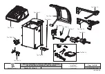
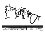
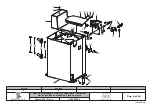
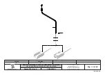
ELECTRICAL AND PNEUMATIC
CONNECTION DIAGRAM
Table N°A - Rev. 0
KEY
1 – CPU Card
2 – Diameter Measurement Potentiometer
3 – Front piezo
4 – Rear piezo
5 – Opening solenoid valve (O)
6 – Closing solenoid valve (C) (only for GP2.124HD)
7 – Distance optical sensor (optional)
8 – Wheel position optical sensor (optional)
9 – Protection guard microswitch
10 – Pneumatic mandrel control pedal microswitch (only
for GP2.124R)
11 – Motor in d.c.
12 – Pneumatic tightening diagram (only for
GP2.124R)
13 – Tightening drive cylinder
14 – 5/2 NC solenoid valves
15 – Separating filter
16 – Display
17 – General disconnecting switch
18 – Supply inlet
19 – 230/24 Vac Transformer
20 – Width Measurement Potentiometer
21 – Functional keyboard
2
1
4
3
5
6
7
8
9
10
11
12
13
14
15
16
17
18
19
20
21
RAVAGLIOLI S.p.A.
1297-M010-0_R
G2.124R - GP2.124R


