GB
Page 56 of 64
INSTRUCTION, USE AND
MAINTENANCE MANUAL
1
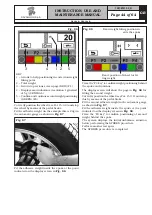
Turn the gauge ferrule (
Fig. 117 ref. 1
) on the inner
edge of the wheel UPWARDS and press “F4”.
Fig.
117
1
KEY
1 – Exit from the gauge calibration procedure and
return to calibration menu page (RED) (F1)
2 – Perform storing of gauge position on “inner edge
of the wheel UPWARDS” (GREEN) (F4)
2
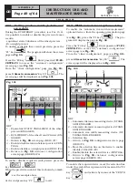
Press "CENTRE" to confirm. Calibration of the distance
and diameter calipers is terminated, The program will
display again the calibration menu page in
Fig. 105
.
1
KEY
1 – Return to previous screen page (RED) (F1)
2 – Perform storing of gauge position (CENTRAL)
2
Fig. 118
IF THE AUTOMATIC RIM WIDTH
MEASURING DEVICE IS ENABLED,
THE CALIBRATION PAGE WILL
APPEAR FOR THIS DEVICE (SEE
PARA. 21.4).
21.4 Automatic rim width measuring device
calibration (optional)
After performing distance and diameter caliper calibra-
tion (see para. 21.3) if the automatic rim width measur-
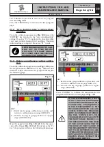
ing device is enabled, the following page will appear:
1
KEY
1 – Exit from the width measurement calibration
procedure and return to calibration menu page
(RED) (F1)
2 – Perform storing of width measuring device posi-
tion on "end of shaft" (GREEN) (F4)
2
Fig. 119
Move the tip of the width measuring device (
Fig. 120A
ref. 1
) by the mandrel end (
Fig. 120A ref. 2
) (in case
of pneumatic mandrel, move it next to upper edge of
the closed mandrel). The program will show the screen
page in
Fig. 120B
.
G2.124R - GP2.124R
RAVAGLIOLI S.p.A.
1297-M010-0_R


