background image

INSTRUCTION, USE AND  

MAINTENANCE MANUAL

GB

Page 33 of 64

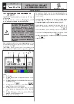
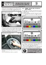
Fig. 60

On reaching the 2 fixed ar-

rows, fit the adhesive weight

The fact that the weight fitting position is no longer at 
12 o’ clock (see 

Fig. 61

) is automatically offset.

If the adhesive weight has to be hidden behind spokes, 
refer  to  “weights  hidden  behind  spokes  mode”  in 
Chapt. 18.

Fig. 61

Fit weight on the position where 
pliers touches the wheel

Check wheel balancing conditions by making a trial 
spin. The display screen will show an unbalance reset.
The STATIC procedure is completed.

15.4  Measuring the unbalance with auxil-

iary programs 

The available functions permit selecting the appropri-
ate weight positions to be placed in positions different 
to the standard ones (dynamic unbalance).
The ALU programs measure rims by means of pre-set 
data in the wheel balancer. 
The measurements entered by the operator will there-
fore be automatically corrected by the machine accord-
ing to the selected program. 
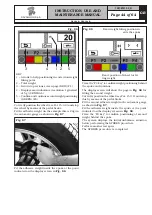
From the program start page, press "F2 key".
The monitor shows a window with possible selection 
modes. Select the desired function by means of the “F3 

key” 

 and enter the measurements.

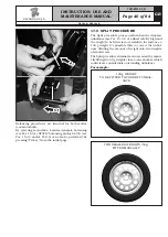
POSSIBLE SELECTABLE FUNCTIONS


The ALU-S 1 function permits balancing wheels with 
light alloy rims by fitting adhesive weights on the outer 
side and weight with clip on inner side of wheel (at 12 
o’ clock). Enter the measurements (see par. 15.1) and 
proceed as described in par. 15.4.1 (the inner weight 
is with clip).

The ALU-S 2 function permits balancing wheels with 
light alloy rims by fitting two adhesive weights on the 
outer and inner sides of the rim (the inner weight is 
at 12 o’ clock).
Enter the measurements (see par. 15.1) and proceed as 
described in par. 15.4.1 (the inner weight is adhesive).

1297-M010-0_R

G2.124R - GP2.124R

RAVAGLIOLI S.p.A.

Summary of Contents for G2.124R

Page 1: ...n LIST OF COMPONENTS enclosed to this manual GB TRANSLATION FROM THE ORIGINAL INSTRUCTIONS G2 124R GP2 124R 1297 M010 0_R 1297 M010 0_R Technical services RAVAGLIOLI S p A Via 1 Maggio 3 40037 Pontecc...

Page 2: ...BALANCING_______________ 24 15 1 Determination of wheel dimensions__ 24 15 1 1 Automatic wheel dimension setting distance and diameter __________ 24 15 1 2 Manual setting of wheel dimensions_________...

Page 3: ...__________________ 63 26 0 SCRAPPING________________________ 63 26 1 Instructions for the correct management of waste from electric and electronic equipment in italian RAEE according to legislative de...

Page 4: ...liper 4 Threaded mandrel only for G2 124R model 5 Protection guard 6 Foot brake only for G2 124R model pneumatic mandrel open close pedal only for GP2 124R model 7 Main switch 8 External data gauge op...

Page 5: ...or jobs to be performed compulsorily Danger Be particularly careful Symbols Description Move with fork lift truck or pallet truck Lift from above 1541000 General danger Wear safety goggles Technical...

Page 6: ...READ IT MUST BE REPLACED QUOTE THE CODE NUMBER WHEN REORDERING 99990114 99990758 999910050 999912940 999914160 999914170 999916310 999920530 Arrow plate Electricity danger plate Protection device use...

Page 7: ...are this wheel balancer will give you many years of trouble free service and lots of satisfaction 2 0 INTENDED USE The models G2 124R GP2 124RMACHINES and relative versions are wheels balancing machin...

Page 8: ...o serious dangers and represents a transgression of European safety rules Use of the machine is only permitted in places free from explosion or fire hazard and in dry places under cover Original spare...

Page 9: ...ipment when the shop is damp or the floor slippery and do not expose such tools to atmospheric agents When operating and servicing this machine carefully follow all applicable safety and accident prev...

Page 10: ...bient conditions other than those specified above is only allowed after prior agreement with and approval of the manufacturer 6 0 UNPACKING DURING UNPACKING ALWAYS WEAR GLOVES TO PREVENT ANY INJURY CA...

Page 11: ...sufficient to guar antee that the anchoring bolts hold 8 2 Lighting The machine does not require its own lighting for normal working operations However it must be used in an adequately lit environmen...

Page 12: ...1 129571492 Gauge 1 1300A004 Weight pliers 1 999072 Carriages counterweight 1 For GP2 124R model Code Description N GAR108 Rapid ring nut pusher ring 1 GAR111 Cones protection cup 1 129571492 Gauge 1...

Page 13: ...pneumatic mandrel always opens when the machine is switched on Switch the ma chine off Fit the internal mandrel on the flange and tighten it with the wrench provided Fig 7 and Fig 8 2 Press the brake...

Page 14: ...y means of the pedal provided and loosen the internal mandrel using the special wrench Fig 9 9 3 3 Fitting of external data gauge option al 1 Unscrew the fastening screws of the equalizer s support Fi...

Page 15: ...ing very careful about holding the same support 2 Unscrew the 3 screws Fig 16 ref 2 to the gauge bracket Fig 16 ref 3 and in the special inserts placed on the rear side of the frame Lock the gauge arm...

Page 16: ...the support Fig 19 ref 2 using the screws Fig 19 ref 3 interposing the Belleville washers Fig 19 ref 4 2 Tighten the screws Fig 19 ref 3 in order to make the guard Fig 19 ref 1 lift or lower without b...

Page 17: ...ies with local and applicable regu lations This operation must be performed by expert and professional personnel FIT A TYPE APPROVED AS RE PORTED BEFORE PLUG TO THE MACHINE CABLE THE GROUND WIRE IS YE...

Page 18: ...ONES AND ACCESSORIES ARE USED MADE SPECIFICALLY FOR USE ON THE WHEEL BAL ANCER Wheel fitting using the cones provided is illustrated be low For alternative fittings using optional accessories refer to...

Page 19: ...e cone outside the wheel 5 Clean the mandrel Fig 24 ref 1 before fitting the wheel 6 Fit the wheel Fig 24 ref 3 with the inside of the rim towards the wheel balancer until the wheel is up against the...

Page 20: ...eel with the inner side of the rim towards the wheel balancer and against the cone Fig 26 Open close the pneumatic mandrel Brake the wheel Fig 27 4 Fit the protection cap Fig 28 ref 1 in the bush Fig...

Page 21: ...ef 1 in the bush Fig 30 ref 2 and bring everything against the wheel Fig 30 Close the pneumatic mandrel by pressing key F4 from the configuration screen play Fig 96 or else close by means of the speci...

Page 22: ...tion push button red 3 Function push button yellow 4 Function push button grey 5 Function push button blue 6 Function push button green 7 Previous page push button 8 Next page print push button 9 Push...

Page 23: ...options Fig 33 1 2 3 4 5 6 7 KEY 1 Start page 2 Display of program configuration screen play RED F1 3 Display of auxiliary programs modes Par 15 4 YELLOW F2 4 Display of cars or motorbike modes Chap...

Page 24: ...the automatic rod the program goes di rectly from the start screen page to the screen page illustrated below Fig 35 Move the automatic rod against the rim inner edge Fig 34 in measurement position an...

Page 25: ...point is given by the display of the detected value static mode Fig 39 Without moving the gauge back to initial position further remove the automatic rod and reach the position to be stored for the se...

Page 26: ...om the start screen page choose the mode to be executed by pressing F3 key e g ALU 3 Fig 43 Remove the automatic rod and reach the position to be stored Maintain this position for a few seconds Acquir...

Page 27: ...ed for instance Fig 38 and Fig 40 press centr key to select the value to be modi fied or to be set the display will show the selected value on a black background and on the right the same value in lar...

Page 28: ...an be used by 4 different users at the same time by selecting the above indicated key several times until the desired user is reached When the user key is pressed the current user number appears on th...

Page 29: ...t indicates the direction in which to move the wheel to fit the weights and how much weight is needed to correct the unbalance see Fig 50 Weight can be determined in grams or ounces in this manual exa...

Page 30: ...ery far from the point where the counterweight is to be positioned Wheel position is over 30 from the exact fitting point When the wheel balancer display screen shows or this means you are not far fro...

Page 31: ...indi cated by an arrow that appears on the side of the wheel on which work is being done When two fixed arrows are reached see Fig 55 fit the weight in the position where the weight pliers touch the...

Page 32: ...until the correct position is achieved for correction of unbalance two horizontal arrows Once correct position has been reached press the pedal brake to stop the wheel Fig 58 3 4 5 6 7 KEY 1 Turn the...

Page 33: ...f pre set data in the wheel balancer The measurements entered by the operator will there fore be automatically corrected by the machine accord ing to the selected program From the program start page p...

Page 34: ...f the rim the inner weight is at 12 o clock Enter the measurements see par 15 1 and proceed as described in par 15 4 1 The ALU 2 function balances wheels with light alloy rims by fitting adhesive weig...

Page 35: ...d correction by means of the F3 key display the ALU 1 function and determine the dimensions of the wheel using the automatic gauge provided see Par 15 1 1 After data entry close the protection guard t...

Page 36: ...adhesive weight on the inner part of the wheel turn the wheel in the direction of the arrows until the correct position is reached the two arrows must be horizontal Remove the automatic gauge and fit...

Page 37: ...r n t o i n i t i a l p r o g r a m p h a s e RED F1 4 Display wheel type measurements CENTRAL 5 Select types of wheels BLUE F3 6 Performs spin with protection guard closed GREEN F4 2 Select the type...

Page 38: ...e program displays the list of auxiliary programs see Par 15 4 At this point select the required program by means of the key if necessary set the new dimensions and press key R again to obtain the wei...

Page 39: ...eck the wheel balancing conditions and make a trial spin The ECO WEIGHT procedure is completed 16 0 WHEEL BALANCING IN MOTOR BIKE MODE By enabling the motorbike wheel balancing function see Fig 100 th...

Page 40: ...Split procedure eliminates errors caused by manu ally fitting two 50 g weights close to one another which could leave considerable outstanding unbalance For example 100 g WEIGHT TO BE FITTED TO CORRE...

Page 41: ...the key relating to the SPLIT function the system will display the page in Fig 78 Fig 78 SPLIT function selected Choose the desired wheel side Press key F2 corresponding to icon to se lect the desired...

Page 42: ...EN F4 1 4 Choose the value of the weights to be fitted and press key F4 to confirm Turn the wheel at the point indicated by the arrows until the correct position has been reached to correct the unbala...

Page 43: ...monitor see Fig 83 Fig 83 Press the F3 key relating to the weights hidden behind spokes mode The program will display the screen page in Fig 84 Move any spoke up to 12 o clock in many cases the positi...

Page 44: ...n in Fig 88 Fig 88 Exact position of wheel for fit ting weight Exact weight fitting position in side the spoke Press the F4 key to confirm weight positioning behind the spoke and continue The display...

Page 45: ...r will show a new key sequence see Fig 90 Fig 90 Next row of keys Press the key relating to the MATCHING function the system will display the page in Fig 91 the MATCHING operation can only be performe...

Page 46: ...f the possible unbalance reduction compared to wheel current situation 2 Current static unbalance value in grams It can be reduced with a further wheel and rim rotation 3 Display again of the page wit...

Page 47: ...width diameter of the rim The weight determining wheel unbalance can be in dicated on the display in gram or ounce measure ment unit The width and diameter can be indicated in inches or mm To change t...

Page 48: ...ENGAGED Motorcycle wheel balancing mode DISEN GAGED 2 ECO WEIGHT function ENGAGED ECO WEIGHT function DISENGAGED 3 Return to Fig 96 screen page RED F1 4 Engage Disengage motorcycle wheel balancing mo...

Page 49: ...he key or When the preview is enabled this is shown by a mark see the example above At the end press key F1 to exit 20 3 Width measurement options setting To enable the automatic rim width measurement...

Page 50: ...limit To change the resolution and lower limit from the opening presentation page see Fig 33 press the F1 key the program will display the page in Fig 96 Press the F2 key Enter password F1 F2 CENTR F3...

Page 51: ...IGHT procedure To set the above values from the opening presentation page see Fig 33 press the F1 key the program will display the page in Fig 96 Press the F2 key Enter password F1 F2 CENTR F3 to acce...

Page 52: ...F3 YELLOW F2 3 For technical assistance only CENTRAL 4 Open close the pneumatic mandrel GREEN F4 2 3 4 Press the F2 key enter the password F1 F2 CENTR F3 the program displays the following page Fig 1...

Page 53: ...US F2 or PLUS F3 key to enter the desired values Press the F4 key to continue The program will show the following display page Fig 108 1 KEY 1 Return to previous screen page RED F1 2 Performs wheel sp...

Page 54: ...re and return to calibration menu page RED F1 2 Perform storing of gauge position on upper edge GREEN F4 2 Move the gauge ferrule Fig 113 ref 1 by the upper edge of the flange Fig 113 ref 2 and press...

Page 55: ...cylindrical part of the bell Fig 115 ref 2 and press the F4 key the program will show the fol lowing display page Fig 115 1 KEY 1 Return to previous screen page RED F1 2 Perform storing of gauge posit...

Page 56: ...TOMATIC RIM WIDTH MEASURING DEVICE IS ENABLED THE CALIBRATION PAGE WILL APPEAR FOR THIS DEVICE SEE PARA 21 4 21 4 Automatic rim width measuring device calibration optional After performing distance an...

Page 57: ...ft CENTRAL 2 Fig 120B Press CENTRE to confirm the measurement The program will display the following page 1 KEY 1 Exit from the width measurement calibration procedure and return to calibration menu p...

Page 58: ...ious screen page RED F1 2 Confirms width measuring device on external flange surface CENTRAL 2 Fig 122B Press CENTRE to confirm the measurement Rim width measuring device calibration is terminated The...

Page 59: ...en fitted properly the data acquisition or measure ment sensor may be faulty E 8 Insufficient weight value in wheel bal ancer calibration During the calibration procedure the machine detects insuffici...

Page 60: ...To guarantee the efficiency and correct functioning of the machine it is essential to carry out daily or weekly cleaning and weekly routine maintenance as described below Cleaning and routine maintena...

Page 61: ...0 Power supply 230V 50 60 Hz 1 ph Balancing precision g 1 Balancing speed rpm 100 Rim width setting inches 1 5 22 Rim diameter setting inches 10 26 Max wheel diameter inside protection inches 40 Max w...

Page 62: ...GB Page 62 of 64 INSTRUCTION USE AND MAINTENANCE MANUAL 1695 718 1161 1175 870 1345 1126 920 1285 96 1050 24 1 Dimensions Fig 123 Optional G2 124R GP2 124R RAVAGLIOLI S p A 1297 M010 0_R...

Page 63: ...aste must be collected separately and taken to dedicated collection and recycling cen tres according to OEM instructions and abiding by national laws The symbol showed in Fig 124 applied on the produc...

Page 64: ...r optional 9 Protection guard microswitch 10 Pneumatic mandrel control pedal microswitch only for GP2 124R 11 Motor in d c 12 Pneumatic tightening diagram only for GP2 124R 13 Tightening drive cylinde...

Page 65: ...E REPLACED THE REPLACEMENT MUST BE CARRIED OUT PROFESSIONALLY QUALIFIED PER SONNEL DIE ZEICHNUNGEN DIENEN NUR ZUR IDENTIFIZIERUNG DER ERSATZTEILE DIE ERSETZUNG MUSS DURCH QUALIFIZIERTES PERSONAL ERFOL...

Page 66: ...GRUPPO AZIONAMENTO FRENO BRAKE OPERATION GROUP SATZ F R BREMSBET TIGUNG GROUPE ACTIONNEMENT FREIN GRUPO ACCIONAMIENTO FRENO Tavola N 9A Rev 0___129690610 14 GRUPPO PEDALE FRENO BRAKE PEDAL UNIT BREMS...

Page 67: ...g 3 di 22 ASSIEME GENERALE MAIN ASSEMBLY GENERALSATZ ASSEMBLAGE GENERAL JUNTO GENERAL Tavola N 1 Rev 0 Tav Tab 2 Tav Tab 3 Tav Tab 4 Tav Tab 5 Tav Tab 6 Tav Tab 7 Tav Tab 8 Tav Tab 9 Tav Tab 10 Tav Ta...

Page 68: ...129690292 5 129793150 6 129793160 7A 129690331 7B 129690380 8 129690152 9A 129690610 9B 129690590 10 129690341 11 129791580 12 129390311 13A 13B 14 129791590 OPT OPT 15 129590710 OPT OPT Tavola N 1 Re...

Page 69: ...S TEILELISTE LISTE DES PIECES DETACHEES LISTA DE PIEZAS Pag 5 di 22 GRUPPO MOTORE MOTOR UNIT MOTORSATZ GROUPE MOTEUR GRUPO MOTOR Tavola N 2 Rev 0 129690073 1 2 3 4 5 6 6 7 8 9 9 10 10 11 12 RAVAGLIOLI...

Page 70: ...DES PIECES DETACHEES LISTA DE PIEZAS Pag 6 di 22 Tavola N 3A Rev 0 129690090 GRUPPO ROTANTE COMPLETO COMPLETE ROTARY UNIT KOMPLETTER ROTIERENDER SATZ GROUPE ROTATIF COMPLET GRUPO GIRATORIO COMPLETO 4...

Page 71: ...DES PIECES DETACHEES LISTA DE PIEZAS Pag 7 di 22 GRUPPO ROTANTE COMPLETO COMPLETE ROTARY UNIT KOMPLETTER ROTIERENDER SATZ GROUPE ROTATIF COMPLET GRUPO GIRATORIO COMPLETO Tavola N 3B Rev 0 129690030 4...

Page 72: ...COMPONENTS TEILELISTE LISTE DES PIECES DETACHEES LISTA DE PIEZAS Pag 8 di 22 GRUPPO FRENO BRAKE UNIT BREMSATZ GROUPE FREIN GRUPO FRENO Tavola N 4 Rev 0 129690292 1 2 3 4 5 6 6 7 7 RAVAGLIOLI S p A 12...

Page 73: ...ES DETACHEES LISTA DE PIEZAS Pag 9 di 22 GRUPPO TELAIO FRAME UNIT RAHMENSATZ GROUPE CHASSIS GRUPO ESTRUCTURA Tavola N 5 Rev 0 129793150 1 2 3 3 3 4 5 6 7 8 7 9 10 10 10 17 10 11 12 13 14 15 16 17 18 1...

Page 74: ...MPONENTS TEILELISTE LISTE DES PIECES DETACHEES LISTA DE PIEZAS Pag 10 di 22 GRUPPO PLANCIA BOARD UNIT BRETTSATZ GROUPE PLANCHE GRUPO TABLERO Tavola N 6 Rev 0 129793160 1 2 2 3 3 4 5 5 RAVAGLIOLI S p A...

Page 75: ...DE PIEZAS Pag 11 di 22 GRUPPO CALIBRO TESTER UNIT KALIBERSATZ GROUPE CALIBRE GRUPO CALIBRE Tavola N 7A Rev 0 129690331 24 14 1 2 3 3 4 5 6 7 8 9 10 11 12 13 15 16 17 18 20 22 23 19 21 26 25 27 28 29...

Page 76: ...DE PIEZAS Pag 12 di 22 GRUPPO CALIBRO TESTER UNIT KALIBERSATZ GROUPE CALIBRE GRUPO CALIBRE Tavola N 7B Rev 0 129690380 1 2 3 4 4 5 6 7 8 9 10 11 12 13 14 15 16 17 18 19 20 21 22 23 24 25 26 27 28 29...

Page 77: ...E DES PIECES DETACHEES LISTA DE PIEZAS Pag 13 di 22 GRUPPO AZIONAMENTO FRENO BRAKE OPERATION GROUP SATZ F R BREMSBET TIGUNG GROUPE ACTIONNEMENT FREIN GRUPO ACCIONAMIENTO FRENO Tavola N 8 Rev 0 1296901...

Page 78: ...PIECES DETACHEES LISTA DE PIEZAS Pag 14 di 22 Tavola N 9A Rev 0 129690610 1 2 3 3 4 5 6 7 8 9 10 10 11 12 13 14 14 15 15 GRUPPO PEDALE FRENO BRAKE PEDAL UNIT BREMSE PEDALSATZ GROUPE P DAL FREIN GRUPO...

Page 79: ...ETACHEES LISTA DE PIEZAS Pag 15 di 22 Tavola N 9B Rev 0 129690590 GRUPPO PEDALE FRENO BRAKE PEDAL UNIT BREMSE PEDALSATZ GROUPE P DAL FREIN GRUPO PEDAL FRENO 22 15 16 14 1 2 3 3 4 5 6 7 8 9 10 10 11 12...

Page 80: ...IECES DETACHEES LISTA DE PIEZAS Pag 16 di 22 GRUPPO IMPIANTO ELETTRICO ELECTRICAL SYSTEM UNIT SATZ VON ELEKTROANLAGE GROUPE INSTALLATION LECTRIQUE GRUPO INSTALACI N EL CTRICA Tavola N 10 Rev 0 1296903...

Page 81: ...IECES DETACHEES LISTA DE PIEZAS Pag 17 di 22 GRUPPO PROTEZIONE RUOTA WHEEL PROTECTION UNIT SATZ F R RADSCHUTZ GROUPE PROTECTION ROUE GRUPO PROTECCI N RUEDA Tavola N 11 Rev 0 129791580 1 1 2 3 5 4 7 9...

Page 82: ...Pag 18 di 22 IMPIANTO SERRAGGIO PNUEMATICO PNEUMATIC TIGHTENING SYSTEM ANLAGE F R PNEUMATISCHE AUFSPANNUNG SYST ME SERRAGE PNEUMATIQUE SISTEMA APRIETE NEUM TICO Tavola N 12 Rev 0 129390311 1 2 2 3 3 7...

Page 83: ...IST OF COMPONENTS TEILELISTE LISTE DES PIECES DETACHEES LISTA DE PIEZAS Pag 19 di 22 DOTAZIONE A A EQUIPMENT AUSSTATTUNG A DOTATION A DOTACION A Tavola N 13A Rev 0 5 4 3 2 1 RAVAGLIOLI S p A 1297 R010...

Page 84: ...IST OF COMPONENTS TEILELISTE LISTE DES PIECES DETACHEES LISTA DE PIEZAS Pag 20 di 22 DOTAZIONE B B EQUIPMENT AUSSTATTUNG B DOTATION B DOTACION B Tavola N 13B Rev 0 1 5 4 3 2 RAVAGLIOLI S p A 1297 R010...

Page 85: ...RE LARGEUR PROFESSIONEL CALIBRE ANCHO PROFESIONAL Tavola N 14 Rev 0 129791590 8 1 2 3 4 15 7 5 13 6 14 9 10 11 11 12 15 16 17 18 19 20 21 22 23 24 25 26 31 27 28 29 30 32 33 33 33 34 34 34 35 36 36 36...

Page 86: ...RO LARGHEZZA WIDTH CALIPER KALIBER F R BREITE CALIBRE LARGEUR CALIBRE ANCHO Tavola N 15 Rev 0 129590710 1 2 3 4 5 6 7 8 9 10 11 13 18 19 20 20 21 22 23 24 24 26 27 27 28 28 29 30 31 32 33 34 38 35 36...

Reviews: