3.2.3
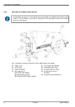
Overview of actuators and sensors
The following overviews do not represent the exact position of actuators and sensors at the
machine. This sub-chapter only serves for information on the assemblies and sensors controlled
by the electronic system.
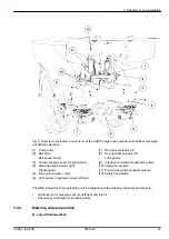
Fig. 5: Overview of actuators and sensors at the AXENT large area spreader
[1]
Hopper cover
[2]
Level sensor
[3]
Vibrator (optional)
[4]
Axis angle sensor
Rear weigh cells, left/right
Steering cylinder (optional)
Steering axle A/B stop valve (optional)
[5]
Front weigh cells, left/right
[6]
Towing bar angle sensor
[7]
Hydraulic block with valves
[8]
Oil temperature sensor
Oil chiller
[9]
Hydraulic circuit floating switch
3. Attachment and installation
24
5901646
AXENT ISOBUS
Summary of Contents for AXENT 100.1
Page 6: ...Table of contents 6 5901646 AXENT ISOBUS...
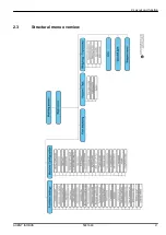
Page 21: ...2 3 Structural menu overview 2 Layout and function AXENT ISOBUS 5901646 21...
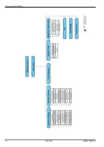
Page 22: ...2 Layout and function 22 5901646 AXENT ISOBUS...
Page 113: ......
Page 114: ......

