background image

HOW TO ORDER PARTS

Parts can be ordered through the supplier from whom
you purchased your log set.
When ordering parts, always specify (From information
available on name plate attached to grate) the following:

1. Model number of the log set.
2. Serial number of the log set.
3. Type of gas (natural or propane Gas).
4. The name of the part and part number from parts list.

Save these instructions

Manufactured By:  RASMUSSEN IRON WORKS,  INC. 

12028 E. Philadelphia Street
Whittier, California  90601

CONSUMER RECORD CARD

Fill in blanks below for your permanent record.

DATE PURCHASED                


MODEL NO.


DATE INSTALLED


S E R I A L   N O .


INSTALLED BY:


G A S   T Y P E :


DEALER:


PARTS LIST C7/DFC7-M/S/R (MANUAL/SWITCH/REMOTE)-N/P 

(NATURAL/PROPANE)

6

7

8

1 0

1 1

1 2

1 3

1 4

2 0

2 1

2 2

3 0

3 1

3 2

2 3

2 4

9

3

2

1

4

5

C7 LOGS

1 2 a

DFC7 LOGS

2 a

1 a

5 a

2 a

4 0

4 1

1.

C7 Center Log C-15

5.

C7 Front  Log

10. ODS Pilot (N or LP

23. Manual  Gas Valve

1a.  DFC7 Center Log (U12a)

H21 (18" Model)

MV or Standard/)

24. Valve Knob

2.

C7 Left Top Log

H22 (24" Model)

11. 1/4" Pilot Supply Tubing

25. Push Button Piezo Ignitor

C-13 (18" or 24" Models)

H23 (30" Model)

12. C7 Grate

C7or DFC7-S (Switch)

C-10 (30" Model)

5a. DFC7 Front  Logs (Two)

12a.DFC7 Grate

30. MV Valve (3.5 or 10.0)

2a.  DFC7  Left and Right Top

H21a (18" Model)

13. Piezo Ignitor

31. 3 Way Switch (S Model)

CH3a (18" Model)

H22a (24" Model)

14. Ember Material

32. 3/8" Valve Output Burner

BE2a (24" or 30" Models)

H23a (30" Model)

C7 or DFC7-M (Manual)

Gas Connector

3.

C7 Right Top Log D8

6.

Burner

20 1/4" Burner Supply  (High)

C7or DFC7-R (Remote)

4.

C7 Rear Log

7.

BurnerOrifice (N or LP)

21. 1/4" Burner Supply  (Low)

40. Remote Valve and

H-24 (18" or 24"Models)

8.

Burner Orifice Holder

receiver

H-26 (30" Model)

9.

3/8" Gas Supply Connect

22. Regulator (N) or (P)

41. Remote transmitter

11

Summary of Contents for CHILLBUSTER Evening Embers 7 Series

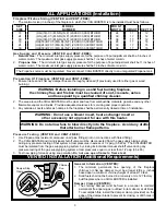
Page 1: ...lace or in a listed ventless firebox enclosure DO NOT install this appliance in a factory built fireplace that includes instructions stating it has not been tested or should not be used with unvented gas logs Do not use this CHILLBUSTER as a Vent Free Heater in sleeping quarters bathrooms or recreational vehicles WARNING If the information in this manual is not followed exactly a fire or explosion...

Page 2: ...es instructions stating it has not been tested or should not be used with unvented gas logs WARNING Any change to this heater or its controls can be dangerous Installation and repair should be done by a qualified service person The appliance should be inspected before use and at least annually by a professional service person More frequent cleaning may be required due to excessive lint from carpet...

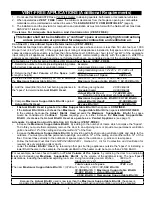
Page 3: ...able vapors and liquids Provide adequate clearances for servicing and proper operation 3 Any outside air ducts and or ash dumps in the fireplace shall be permanently closed at time of installation WARNING Do not use a blower insert heat exchanger insert or other accessory not approved for use with this heater WARNING Do not allow fans to blow directly into the fireplace Avoid any drafts that alter...

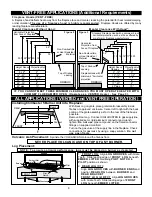
Page 4: ...e Btu Hr against Actual Btu hr Used Maximum Supportable Btu Hr 60 160 Btu Hr Actual Btu Hr Used 72 000 Btu Hr Excess Btu Hr 11 840 Btu Hr If Actual Btu Hr Used is greater than Max Supportable Btu Hr then space is CONFINED If the Actual Btu Hr Used is less than Maximum Supportable Btu Hr then space is UNCONFINED In the example because the Actual Btu Hr Used exceeds the Maximum Supportable Btu hr th...

Page 5: ... floors between wall panels at penetrations for plumbing electrical and gas lines and at other openings WARNING CARBON MONOXIDE POISONING MAY LEAD TO DEATH When used without fresh air gas log sets may give off carbon monoxide an odorless colorless poisonous gas Some people pregnant women persons with heart or lung disease anemia or under the influence of alcohol and persons at high altitudes are m...

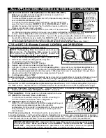
Page 6: ...IMNEY FLUE DAMPER OPEN Operate as a VENTED Heater See Page 3 ALL APPLICATIONS VENTED and VENT FREE OPERATION Installing Chillbuster 5 Burner Unit Into Fireplace FRONT REAR C L Gas Connect Rear Log With Rear Log on grate place grate control assembly inside firebox or approved enclosure Center left to right with the back portion of the grate assembly as far to the rear of the firebox as possible Rem...

Page 7: ...ion as shown 2 CENTER LOG Using the log locator hole and pin place the CENTER LOG onto the CENTER PIN of REAR LOG C7 or on the two FRONT LOG pins DFC7 WARNING Failure to position parts in accordance with these diagrams or failure to use only parts specifically approved with this heater may result in property damage or personal injury Volcanic Ash Placement Place VOLCANIC ASH only on the firebox fl...

Page 8: ... until all air is bled and gas flows to pilot 6 Press Piezo Ignitor Button Figure 3 to light pilot Continue to hold in Primary Gas Valve Control Knob until the Pilot flame remains lit when knob is released approx 60 to 90 seconds If Pilot does not remain lit repeat steps 1 through 5 and allow additional time after Figure 8 ON POSITION v OFF POSITION v PILOT POSITION PILOT v PILOT ADJUST COVER CAP ...

Page 9: ...N Once pilot lights continue to hold in Operating Dial until the Pilot flame remains lit when knob is released approximately 60 to 90 seconds If Pilot does not remain lit repeat steps 1 through 5 and allow more time after Pilot Lighting before releasing knob Figure 9 6 Turn Operating Dial to ON Ignition Interlock The Ignition Interlock device prevents the re establishment of gas flow following a l...

Page 10: ...d of debris Use compressed air or a soft bristle brush to clear pilot and burner s air intakes Air shutters should not be altered from factory settings WARNING Failure to keep the primary air opening s of the burner s clean may result in sooting or property damage Obstructed Pilot Air Intake Ports result in an improper gas air mixture and a weak pilot flame Weak pilot flame is the NUMBER 1 SERVICE...

Page 11: ... 2 1 4 5 C7 LOGS 12a DFC7 LOGS 2a 1a 5a 2a 40 41 1 C7 Center Log C 15 5 C7 Front Log 10 ODS Pilot N or LP 23 Manual Gas Valve 1a DFC7 Center Log U12a H21 18 Model MV or Standard 24 Valve Knob 2 C7 Left Top Log H22 24 Model 11 1 4 Pilot Supply Tubing 25 Push Button Piezo Ignitor C 13 18 or 24 Models H23 30 Model 12 C7 Grate C7or DFC7 S Switch C 10 30 Model 5a DFC7 Front Logs Two 12a DFC7 Grate 30 M...

Page 12: ...y as set forth herein and applies only for the periods designated above 2 RASMUSSEN shall not be liable for any loss damage incidental or consequential damages of any kind whether based upon warranty contract or negligence arising in connection with the sale use or repair of the product Some states do not allow the exclusion or limitation of incidental or consequential damages so the above limitat...

Page 13: ...CHANGES next Consolidate C7 and DFC7 page 1 standard update z21 11 2a 2001 DUE 4 03 standard update z21 11 2b 2002 DUE 12 03 Title change Customer Responsibilities And Annual Maintenance page 10 13 ...

Reviews: