background image

Operating the instrument

R&S

®

RTE

107

Getting Started 1326.1026.02 ─ 10

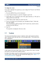
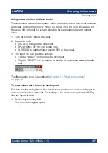
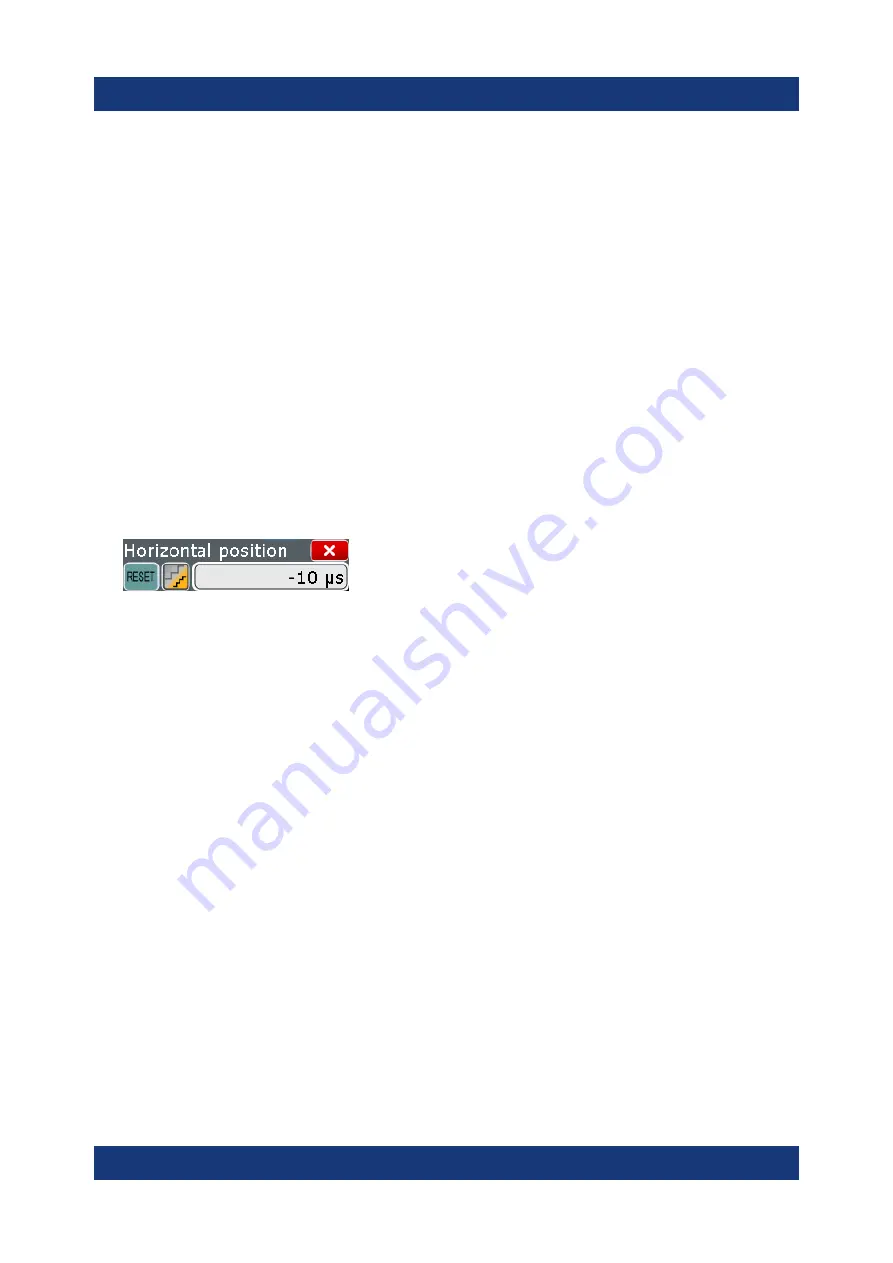
Using scale, position and level knobs

The instrument has dedicated rotary knobs to set vertical and horizontal positions
and scale, and the trigger level. When you turn a knob, the input box appears in
the upper left corner of the screen, showing the parameter name and current
value.

1. Turn the knob to change the value.

2. Press the knob:

● [SCALE]: to toggle the increment.
● [POSITION / OFFSET]: to set to zero.
● [LEVELS]: to set the trigger level to 50% of the signal.

3. The input box also provides settings

● Tap the "Steps" icon to toggle the increment.
● Tap the "RESET" icon to set the parameter to the autoset value (if availa-

ble).

The [Navigation] knob is described in 

Chapter 5.3, "Keys and controls"

,

on page 33.

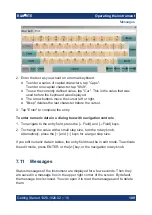
To enter values with the on-screen keypad

For data input in dialog boxes, the touchscreen provides an on-screen keypad to
enter numeric values and units. For text input, the on-screen keyboard with Eng-
lish key layout is used.

1. Double-tap the entry field.

The on-screen keypad opens.

Entering data

Summary of Contents for RTE

Page 1: ...R S RTE Oscilloscope Getting Started 1326102602 Version 10 J J2 Sie haben Fragen oder w nschen eine Beratung Angebotsanfrage unter 49 7121 51 50 50 oder ber info datatec eu Distributed by...

Page 2: ...17 2500K02 R S RTE1104 1 GHz 4 channels 1326 2000K64 and 1317 2500K04 R S RTE1152 1 5 GHz 2 channels 1326 2000K72 R S RTE1154 1 5 GHz 4 channels 1326 2000K74 R S RTE1202 2 GHz 2 channels 1326 2000K82...

Page 3: ...rument help 16 3 2 Data sheet and brochure 17 3 3 Release notes open source acknowledgment 17 3 4 Application notes application cards videos 17 4 Preparing for use 18 4 1 Lifting and carrying 18 4 2 U...

Page 4: ...8 Performing mathematical calculations 68 6 9 Performing a search 70 6 10 Performing a mask test 71 6 11 Printing and saving screenshots 74 6 12 Saving data 77 7 Operating the instrument 80 7 1 Means...

Page 5: ...Contents R S RTE 5 Getting Started 1326 1026 02 10 8 1 Performing a self alignment 113 8 2 Setting the display language 114 8 3 Adjusting passive probes 114 9 Contacting customer support 116 Index 117...

Page 6: ...Contents R S RTE 6 Getting Started 1326 1026 02 10...

Page 7: ...potential dangers and gives instructions on how to prevent personal injury or damage caused by dangerous situations Safety information is provided as follows In Chapter 1 1 Safety instructions on pag...

Page 8: ...lf Use the instrument handles to move or carry the instrument Do not use the mounted accessories instead of the handles Accessories are not designed to carry the weight of the instrument To move the i...

Page 9: ...cting to power and grounding The mains power supply input of the instrument complies with overvoltage cate gory II It has to be connected to a fixed installation used to supply energy con suming equip...

Page 10: ...ed the value specified in the data sheet Observe all voltage and current ratings of the instrument the probes and the accessories Limits and ratings are marked on the products and listed in the data s...

Page 11: ...ive measures to pre clude direct contact with the measurement setup Do not touch exposed connections and components when power is applied Switch off the test circuit while connecting and disconnecting...

Page 12: ...out rated measurement category For measurements performed on circuits not directly connected to mains for example electronics circuits powered by batteries and specially protected secondary circuits T...

Page 13: ...uctor terminal Connect this terminal to a grounded external conductor or to protective ground This protects you against electric shock should an electric problem occur 1 2 Labels on the product Labels...

Page 14: ...afety hazard and how likely it will occur if you do not follow the safety precautions WARNING Potentially hazardous situation Could result in death or serious injury if not avoi ded CAUTION Potentiall...

Page 15: ...tion rate and shortest blind time Access and analyze prior waveforms in the memory using the history function Get fastest results even with maximum data with hardware accelerated pro cessing mathemati...

Page 16: ...to the complete information for the firmware basic functionality and applications User manual Describes all instrument functions in detail It also provides an introduction to remote control a complet...

Page 17: ...brochure pro vides an overview of the instrument and deals with the specific characteristics See www rohde schwarz com brochure datasheet rte 3 3 Release notes open source acknowledgment The release n...

Page 18: ...cking material Use it when transporting or shipping the product later 3 Using the delivery notes check the equipment for completeness 4 Check the equipment for damage If the delivery is incomplete or...

Page 19: ...equipment causes radio disturbances take appropriate measures to eliminate them 4 4 Setting up the product When setting up the instrument follow the safety instructions Setting up the product on page...

Page 20: ...2 Mounting the product in a rack The instrument can be installed in a rack using a rack adapter kit The order num ber is given in the data sheet The installation instructions are part of the adapter...

Page 21: ...pter kit 4 5 Considerations for test setup Observe safety instructions see Performing measurements on page 10 Cable selection and electromagnetic interference EMI Electromagnetic interference EMI can...

Page 22: ...some hardware components and initiates a new alignment to ensure proper instrument functioning Then it restores the user settings to the state before the disturbance 4 6 Connecting to power For safet...

Page 23: ...ly to position I The power key on the front panel lights up 2 Press the POWER key on the front panel The instrument performs a system check boots the operating system and then starts the R S RTE firmw...

Page 24: ...ment Connecting USB devices 24 Connecting an external monitor 26 4 8 1 Connecting USB devices The USB interfaces on the front and rear panels allow you to connect USB devi ces directly to the instrume...

Page 25: ...configured in the operating system not in the R S RTE software It is recommended that you use mouse and key board to access and modify the settings of the Windows operating system To access Windows pr...

Page 26: ...le MONITOR DVI D on page 32 Before connecting an external monitor ensure that the monitor and the R S RTE are connected to a ground contact Otherwise the instrument can be damaged After connecting an...

Page 27: ...Many external monitors have a higher screen resolution If the screen resolution of the monitor is set higher than the instrument s resolution the application win dow uses a 1024 x 768 area of the moni...

Page 28: ...and connectors 5 1 Front panel The front panel of the R S RTE is shown in Figure 5 1 The function keys are grouped in functional blocks to the left and the right of the touchscreen Below the screen va...

Page 29: ...z active probe interface and they are BNC compatible Thus the instrument can automatically detect passive probes with standard BNC connector and active Rohde Schwarz probes having the Rohde Schwarz pr...

Page 30: ...ts To avoid any impact do not use USB connecting cables exceeding 1 m PROBE COMPENSATION Probe compensation terminal to support adjustment of passive probes to the oscilloscope channel Protective eart...

Page 31: ...re or waveform generator R S RTE B6 or GPIB connector R S RTE B10 9 Kensington lock slot to secure the instrument against theft 10 Lugs to attach the accessory bag AC power supply connector and main p...

Page 32: ...ed to provide the internal trig ger signal of the oscilloscope to trigger other instruments for synchronized mea surements When a trigger occurs the R S RTE creates a pulse of 5 V with a source impe d...

Page 33: ...y for a signal with the minimum input voltage swing of 500 mV Vpp is 400 MHz For detailed specifications refer to the data sheet Waveform generator option R S RTE B6 The waveform generator generates v...

Page 34: ...configurations and save them to a file The PRESET key can be configured to set either factory defaults or a user defined preset configuration FILE Opens and closes the File dialog box where you can S...

Page 35: ...een is off the key is illuminated Press again to unlock the touchscreen INTENSITY Adjusts the intensity of the waveforms on the screen or the background transpar ency of dialog boxes or the transparen...

Page 36: ...toggle the setting The controlled parameter and its value are shown in the input box in the upper left corner of the screen For resolution turn clockwise to increase the resolution the time between t...

Page 37: ...s of the reference point SCALE The rotary knob adjusts the time scale for all signals The time scale is also known as timebase Turn clockwise to stretch the waveforms Doing so the scale value time div...

Page 38: ...are illuminated in brown default color the brightness of the color depends on the selected waveform POSITION OFFSET upper knob The upper rotary knob changes the vertical position or the offset of the...

Page 39: ...LEVELS The rotary knob sets the trigger level for all trigger types Turn clockwise to move up the trigger level If the selected trigger type requires two trigger levels upper and lower level press the...

Page 40: ...ck provide direct access to measure ment and analyzing functions If you press CURSOR ZOOM or MEAS the action starts on first keypress and a second keypress opens the corresponding dialog box If you pr...

Page 41: ...m dialog box opens where you can configure several zoom areas for detailed signal observation PROTOCOL Opens the Protocol dialog box which contains the configuration of serial buses and the settings f...

Page 42: ...nd information The key is illuminated as long as a history acquisition or replay is displayed 5 3 7 NAVIGATION controls The rotary knob and the navigation keys provide an alternative way to navigate i...

Page 43: ...the next cell Field left Field right In dialog boxes and tables the keys move the focus In diagrams they switch the focus between zoom areas cursor lines and gates Checkmark The checkmark key has diff...

Page 44: ...elect an option In an open selection list the keys scroll the list Left arrow Right arrow The left and right arrow keys have the following effects In edit fields move the cursor In tables scroll horiz...

Page 45: ...ts Try out the following Displaying a basic signal 45 Acquiring data 47 Changing the waveform scaling and position 48 Zooming into the display 54 Displaying the waveform history 56 Showing basic measu...

Page 46: ...4 If necessary compensate the passive probe as described in Chapter 8 3 Adjusting passive probes on page 114 5 In the TRIGGER area of the front panel press the SOURCE key Press the key again to switc...

Page 47: ...r aver age waveforms If you need to change only one setting during analysis and you need to change it often you can reduce the dialog box to a small box that only contains the required setting Thus yo...

Page 48: ...Tap the Maximize icon in the mini dialog box The complete Acquisition dialog box is restored 8 Close the dialog box by tapping 6 3 Changing the waveform scaling and position As you can see on the y ax...

Page 49: ...quickly find the new trigger level and try out the scaling functions 1 Press the Ch1 key on the front panel in the VERTICAL area to display the Vertical dialog box 2 Change the Coupling to AC Close th...

Page 50: ...ress the Ch1 key again b Enter 0 V in the Offset field The waveform is now displayed in the center of the display with the x axis crossing at 0 V The waveform can be unstable if the trigger level is a...

Page 51: ...instrument R S RTE 51 Getting Started 1326 1026 02 10 5 Tap the Find level icon on the toolbar The instrument adjusts the trigger level and a stable waveform is displayed Changing the waveform scalin...

Page 52: ...ore detail turn the horizontal Scale rotary knob The current scale factor per division is displayed in the upper left hand corner of the display while you turn the knob You can switch between a small...

Page 53: ...you perform a different action Tip Instead of using the UNDO and REDO keys you can tap the corre sponding icons on the toolbar If you use a Rohde Schwarz active single ended probe you can measure the...

Page 54: ...the default signal channel settings by pressing the PRESET and AUTOSET keys 2 On the toolbar tap the Zoom icon 3 Tap the position in the diagram that you want to define as one corner of the zoom area...

Page 55: ...om window and make room on the display for other results tap the Delete icon and then the zoom window 6 4 2 Using the fingertip zoom 1 Touch the Zoom icon on the toolbar and drag it down until the Zoo...

Page 56: ...ip zoom into a standard zoom diagram 6 5 Displaying the waveform history During a continuous acquisition the instrument stores the acquired data in the memory and shows the current acquisition on the...

Page 57: ...ess History dialog box appears and the history mode is on 6 Tap Play The 10 stored waveforms are displayed one after the other but very fast 7 In the Current acq field enter 4 to display the sixth wav...

Page 58: ...sult table corresponds with the source waveform color 6 6 1 Performing a cursor measurement 1 Restore the default signal channel settings Press the PRESET and AUTOSET keys 2 Tap the Cursor icon on the...

Page 59: ...oss on the icon label 6 6 2 Performing automatic amplitude measurements You can start up to 8 automatic measurements to run in parallel The Automatic measurment icon starts the measurements one after...

Page 60: ...t of the low signal level is started 4 Tap the Automatic measurement icon again Then tap the waveform By default the amplitude measurement is started 5 Double tap the results to open the Measurements...

Page 61: ...measurement A set of up to eight different measurements on one source can be performed at once simply by tapping the Quick measurement toolbar icon The results are displayed in a result box You can co...

Page 62: ...uick measurement 4 Tap the icon to open the Measurements dialog box 5 Select the Quick Meas Setup 6 Scroll down in the table and disable the Mean and RMS measurements 7 Tap Activate and select Period...

Page 63: ...default quick measurement and can be repeated until you save another configuration 10 Close the dialog box 11 To save space in the display minimize the result box The most important results are displ...

Page 64: ...ment values statisti cally 1 Tap the Histogram icon on the toolbar 2 Tap the diagram in which you want to generate the histogram You can also draw a rectangle on the screen to define the area on which...

Page 65: ...histogram is displayed 5 To get more measurement results for the histogram double tap the results Alternatively you can press the MEAS key on the front panel 6 For Meas 2 select Category Hist and the...

Page 66: ...nal in the time domain is converted to a spectrum of frequencies A basic spectrum waveform can be displayed quickly 1 Restore the default signal channel settings by pressing the AUTOSET key 2 Tap the...

Page 67: ...easurement icon on the toolbar 4 Tap the spectrum waveform The channel power is displayed below the FFT diagram 5 Double tap the spectrum waveform The FFT Setup dialog box opens 6 Set the Center frequ...

Page 68: ...s 6 8 Performing mathematical calculations In addition to the measured waveforms you can display calculated data to com pare the current measurement result with For example you can rescale the wavefor...

Page 69: ...the dialog box and note that the instrument adjusts the Vertical scale and Vertical offset of the math waveform automatically 8 Tap Enable to display the first math waveform The original and the resca...

Page 70: ...age 61 1 Press the SEARCH key on the front panel ANALYSIS area 2 Select C1 as Source 3 Select the search criteria Enable Window 4 In the Window tab below define the search conditions a In the Upper le...

Page 71: ...tical lines indicate the time values for which a result was found 8 In the results table tap the row of the search result that you want to display in the search zoom diagram 6 10 Performing a mask tes...

Page 72: ...Definition tab 5 If necessary correct the mask segment points you defined graphically in the Mask Definition tab In the Region column of the mask segment Inner is selected That means a mask hit is det...

Page 73: ...est has failed if the number of sample hits exceeds the limit of Violation tolerance hits 10 Select the Event Action Reset tab 11 For the Stop acquisition action select On violation If the violation t...

Page 74: ...your results In the following examples you print the current display as a black and white graphic with inverted colors i e a black waveform is printed on a white background Then you save some screensh...

Page 75: ...ap the upper left button and select the printer 5 Tap Print The result is a monochrome image 6 Close the dialog box To configure the PRINT key 1 Open the File menu and tap Frontpanel Setup 2 Select th...

Page 76: ...the PRINT key The files are saved to the following directory C Users Public Public Documents Rohde Schwarz RTx ScreenShots The default file name is Screenshot_ date _ index _ time png 4 To access the...

Page 77: ...FILE key on the front panel in the SETUP area on the left 2 Select Waveform 3 Check the Source 4 Set Scope to Full Waveform Tip If a cursor zoom or measurement gate is defined you can use these set ti...

Page 78: ...ogging to enable export all waveforms of a running acquisition d Enter Acq count 10 the number of subsequent waveforms that the instrument acquires and saves 4 Tap Start Export to save the waveforms t...

Page 79: ...ving and restoring device settings 1 Press the FILE key on the front panel 2 Select Savesets 3 Tap Save As Enter the path and filename C Users Public Public Documents Rohde Schwarz RTx SaveSets Settin...

Page 80: ...computers with non Windows operating systems a remote desktop connection is possible using RDP applications For details refer to the user manual chapter Remote Desktop Connection Remote monitoring an...

Page 81: ...tion keys and rotary knobs The front panel provides nearly all functions and controls to operate the instru ment in the classic ways without touchscreen As an exception the signal bar cannot be used w...

Page 82: ...waveform 3c 4 Trigger level 5 Trigger position 6 Reference point distance from trigger position to reference point horizontal position 7 Zoom area 8 Zoom diagram 9 Histogram area 10 Histogram 11 Mess...

Page 83: ...ws the vertical and horizontal divisions The division lines are labeled with the correspondent values The grid labels have the color of the waveform to which they belong If several waveforms are shown...

Page 84: ...ition 3 Offset 4 Coupling 5 Clipping indication is shown if the signal is clipped at the top and or bottom You can also adjust the behavior of the signal bar in various ways see Chap ter 7 6 Using the...

Page 85: ...ilities are described in detail in the User Manual chapter Zoom Histogram and histogram area 9 10 A histogram shows the frequency of occurrence of voltage or time values in a bar chart directly in the...

Page 86: ...dialog box Not shown Input box Toolbar 1 The icons on the toolbar provide quick and easy access to the most important functionality For a detailed description refer to Chapter 7 7 Toolbar on page 94...

Page 87: ...The usage of dialog boxes is described in Chapter 7 9 Using dialog boxes on page 104 Input box The input box appears if you adjust a value using one of the rotary knobs or if you drag an element on th...

Page 88: ...ence for comparison and analysis Math waveforms Eight mathematic waveforms can be created with mathematic operations per formed on channel reference and other math waveforms Zoom waveforms Show the de...

Page 89: ...r one above the other To change the diagram name double tap the tab name The Rohde Schwarz SmartGrid function helps to arrange the diagrams Waveform states Depending on its place on the screen and the...

Page 90: ...eference or math waveform press the correspond ing key Tap the signal icon Note Zoom waveforms in zoom diagrams cannot be selected To minimize a waveform Choose on of the following ways Tap the Minimi...

Page 91: ...to create and arrange the diagrams on the screen with drag drop The diagram layout depends on the position where you drop the signal icon in relation to an existing diagram Figure 7 5 SmartGrid positi...

Page 92: ...in an existing or in a new diagram and it is selected for further actions 3 To change the size of the new diagram drag its edge to the required position 7 6 Using the signal bar The signal bar can ho...

Page 93: ...p of the signal bar and drag it to the opposite side of the screen To configure auto hide The signal bar can be hidden if the displayed information has not changed for a defined time and is displayed...

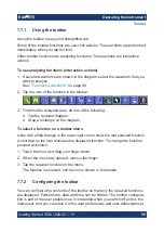
Page 94: ...Colors Define the new color settings To see the effect of a setting change in the Preview area enter the value and press the ENTER key 6 Tap OK The signal bar is displayed in the new colors 7 7 Toolb...

Page 95: ...required diagram Drag a rectangle on the diagram To select a function on a toolbar menu Icons with a little triangle in the lower right corner show the last selected function A short tap on the icon a...

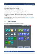
Page 96: ...ctions that you want to add to the toolbar To display all available toolbar icons tap Show All To hide all toolbar icons tap Hide All 3 To hide the current date and time on the toolbar disable Show da...

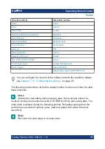
Page 97: ...pectrogram option R S RTE K18 You can configure the content of the toolbar and hide the date time display see Chapter 7 7 2 Configuring the toolbar on page 95 The following list describes at first the...

Page 98: ...the last selected zoom type A short tap on the icon activates the selected zoom If you touch the icon and drag your finger down a menu opens where you can select another zoom type Standard zoom Zoom D...

Page 99: ...h is performed on the selected waveform Cursor The cursor icon shows the last selected cursor type A short tap on the icon activates the selected cursor If you touch the icon and drag your finger down...

Page 100: ...be measured To define a measurement gate draw a rectangle on the screen To modify the measurement tap the icon in the Measurement result box Quick meas Performs a set of measurements on the selected w...

Page 101: ...ong term measurement and statistics all waveforms and the history Autoset and Preset Performs an autoset or a preset to a default state The icons have the same functionality as the corresponding keys...

Page 102: ...he waveform data to file using the settings defined in FILE Waveforms Results Waveforms The filename is created according to the autonaming pattern Tap the icon and then tap the waveform to be exporte...

Page 103: ...on the screen If the results are docked touch a result line and drag it The SmartGrid indicates where the result box will be placed If you drop the box on one of the buttons the results are shown in a...

Page 104: ...nu Label Display Result position Note Once you undock the measurement results you cannot move the result box back to the docked position To define the default position of other results mask test searc...

Page 105: ...actions Tap the required menu and then the menu entry Press the function key on the front panel If a results box is open tap the icon to open the corresponding dialog box To open the Vertical dialog...

Page 106: ...select an option in a list If many options are available for example for the trigger type the options are provided in a list The current selection is shown on the list button Tap the list button Then...

Page 107: ...increment POSITION OFFSET to set to zero LEVELS to set the trigger level to 50 of the signal 3 The input box also provides settings Tap the Steps icon to toggle the increment Tap the RESET icon to se...

Page 108: ...between small steps and large steps tap the Steps icon To get the value that was used before the keypad was displayed tap Cur To enter a user defined value tap the numbers and complete the entry by ta...

Page 109: ...nter numeric data in a dialog box with navigation controls 1 To navigate to the entry field press the Field and Field keys 2 To change the value with a small step size turn the rotary knob Alternative...

Page 110: ...ation on the instrument s functionality you can use the following sources Tooltips give a short description of the parameter The context help provides functional description on a setting and the corre...

Page 111: ...en If a dialog box is open the help topic for the current tab is shown Otherwise the Contents page appears 7 12 2 Using the help window The Help window contains several tabs View shows the selected he...

Page 112: ...rch tab 2 Select the Keyboard icon besides the entry field 3 Enter the string you want to find If you enter several strings with blanks between topics containing all words are found same as AND operat...

Page 113: ...ent into operation for the first time After a firmware update Once a week When major temperature changes occur 5 1 Warm up the instrument before you start the self alignment The minimum warm up time i...

Page 114: ...oscilloscope input capacitance to assure good amplitude accuracy from DC to upper bandwidth limit frequencies A poorly compensated probe reduces the performance of the probe oscilloscope system and in...

Page 115: ...Setting up the instrument R S RTE 115 Getting Started 1326 1026 02 10 Adjusting passive probes...

Page 116: ...ct contact our customer support center A team of highly qualified engineers provides support and works with you to find a solution to your query on any aspect of the operation program ming or applicat...

Page 117: ...ar panel 30 USB 29 Coupled zoom quick access 98 CURSOR key 40 Cursors Minimizing results 58 Quick access 99 Trying out 58 Customer support 116 D Data entry 106 Data sheet 17 Decimation 47 Delete 100 D...

Page 118: ...ector 32 Language Changing 114 LEVELS knob 39 Lock touchscreen 35 LOGIC key 42 Logic probe connector 33 M Markers Example 54 Mask test Quick access 99 Trying out 71 MASKS key 41 MATH key 38 Math wavef...

Page 119: ...otes 17 Remote control 80 Find command using help 110 Remote Desktop 80 Remote operation 80 RES REC LEN key 36 Resolution Rotary knob 36 Result boxes 85 Background transparency 35 Displaying 102 Resul...

Page 120: ...t 100 Show signal bar 98 Show tooltips 97 Undo 97 Zoom 98 Tooltips 97 Show 110 Touchscreen Compared with mouse 80 Control elements 85 Lock unlock 35 Usage 80 Transparency 35 Trigger Controls 39 Extern...

Page 121: ...eforms 88 Z Zoom Area 85 Diagram 85 Fingertip 55 Quick access 98 Standard 54 Trying out 54 Waveforms 88 ZOOM Key 41 Sie haben Fragen oder w nschen eine Beratung Angebotsanfrage unter 49 7121 51 50 50...

Reviews: