Remote Control Commands
R&S
®
NGL200/NGM200
95
User Manual 1178.8736.02 ─ 05
7.4
Trigger Commands
The
TRIGger
subsystem contains the commands for signal triggering.
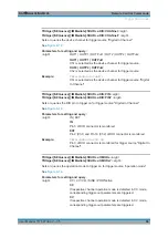
TRIGger[:SEQuence][:IMMediate]:SOURce
........................................................................ 95
TRIGger[:SEQuence][:IMMediate]:SOURce:DIO:CHANnel
...................................................96
TRIGger[:SEQuence][:IMMediate]:SOURce:DIO:PIN
........................................................... 96
TRIGger[:SEQuence][:IMMediate]:SOURce:OMODe
........................................................... 96
TRIGger[:SEQuence][:IMMediate]:SOURce:OMODe:CHANnel
.............................................97
TRIGger[:SEQuence][:IMMediate]:SOURce:OUTPut:CHANnel
............................................. 97
TRIGger[:STATe]
<arg0>
Enables or disables the trigger system.
Upon being triggered, the selected trigger source
See
Setting parameters:
<arg0>
1 | 0
1
Enables the trigger system.
0
Disables the trigger system.
TRIGger[:SEQuence][:IMMediate]:SOURce
<arg0>
TRIGger[:SEQuence][:IMMediate]:SOURce?
<arg0>
Sets or queries the trigger source.
See
Parameters for setting and query:
<arg0>
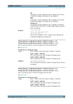
OUTPut | OMODe | DIO
OUTPut
Trigger source is from the output channel (Ch1, Ch2).
OMODe
Trigger source is from the different modes (CC, CR, CV, Sink,
OVP, OCP, OPP and OTP) detected from the output channel
(Ch1, Ch2).
DIO
Trigger source is from DIO connector at the instrument rear
panel.
Example:
TRIG:SOUR OMOD
Trigger source "Operation Modes" is selected for monitoring.
Trigger Commands


