Common Analysis and Display Functions
R&S
®
FSVA3000/ R&S
®
FSV3000
448
User Manual 1178.8520.02 ─ 01
9.3.4.3
Phase Noise Measurement Marker
Access
: "Overview" > "Analysis" > "Marker Functions" > "Phase Noise" > "Phase
Noise Config"
Or
: [MKR FUNC] > "Select Marker Function" > "Phase Noise" > "Phase Noise Config"
For each of the 16 markers phase noise measurement can be activated.
Phase noise is unintentional modulation of a carrier; it creates frequencies next to the
carrier frequency. A phase noise measurement consists of noise density measure-
ments at defined offsets from the carrier; the results are given in relation to the carrier
level (dBc). The phase noise marker function measures the noise power at the delta
markers referred to 1 Hz bandwidth. Marker 1 is used as the reference for the phase
noise measurement. By default, the current frequency and level of marker 1 are used
as the fixed reference marker. However, a peak search can be started to use the cur-
rent signal peak as the reference point, or a reference point can be defined manually.
Since the reference point is fixed, the reference level or the center frequency can be
set so that the carrier is outside the displayed frequency range after phase noise mea-
surement is started. Or a notch filter can be switched on to suppress the carrier.
Alternatively, the reference point can be determined automatically by a peak search
after each sweep. This function can be used to track a drifting source during a phase
noise measurement. The delta marker 2, which shows the phase noise measurement
result, keeps the delta frequency value. Therefore the phase noise measurement leads
to reliable results in a certain offset although the source is drifting. Only if the marker 2
reaches the border of the span, the delta marker value is adjusted to be within the
span. In these cases, select a larger span.
The result of the phase noise measurement is the difference in level between the refer-
ence point and the noise power density. It is indicated as the function result of the
phase noise marker in the marker table.
The sample detector is automatically used and the video bandwidth set to 0.1 times the
resolution bandwidth (RBW). The two settings are taken into account in the correction
values used for the noise power measurement. To obtain stable results, two pixels on
the right and the left of the delta marker position are taken for the measurement.
The procedure for determining the noise power is identical to the method used for the
noise power measurement (see
Chapter 9.3.4.2, "Measuring Noise Density (Noise
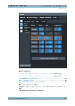
The individual marker settings correspond to those defined in the "Marker" dialog box.
Any settings to the marker state or type changed in the "Marker Function" dialog box
are also changed in the "Marker" dialog box and vice versa.
Marker Usage

