R&M Materials Handling, Inc
STAGEMAKER
®
Concert Hoist
Springfield, Ohio USA
Technical Guide
:
800 955-9967
June 2009
www.rmhoist.com
RM-STGMKR-TG-2002-6-ENG.doc
17
®
3.5 Hoist
Configuration
E
– Without Motor Controls
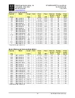
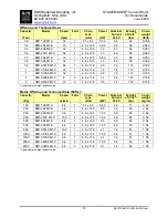
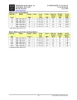
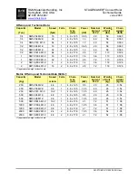
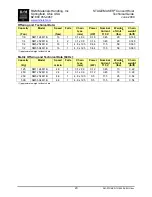
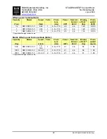
Configuration E utilizes three-phase power and is set up for external controls (typically VFD), which are
not included. The hoist is equipped for fixed installations so it can be mounted in the normal position, but
when specially equipped the hoist can also be mounted in the inverted position.
Hoist features for normal mounting position:
Black load chain
Non-reflecting matt black finish
Fixed body hook
Standard chain guide
Disc brake
Brake rectifier
Torque limiting device
Upper and lower electrical limit switches (weight-operated)
Steel control enclosure
Chain container for 100 ft [30 meters] of load chain
No controls
Wiring to terminal strip
Two round cable glands - 5/16”-9/16” [8-15 mm] diameter cable
230V-3Ph-60Hz power supply
Available options:
Inverted mounting position - includes a Chainflux chain guide, handgrips, and a swiveling
body hook. Upper and lower electrical limit switches (weight-operated) are removed and a
geared limit switch is added.
Sensor bearing with filter for positioning/speed supervision - for inverter control
Geared limit switch
Vinyl rain cover
Drain hole in the load sprocket compartment
Second brake
Self locking hook
460V-3Ph-60Hz or 208V-3Ph-60Hz power supply
Handgrips
Note:
With inverter control, a separate contactor must be used to activate the brake.
The maximum frequency (Hz) that could be applied to the motor is noted in the applicable
Offering and Technical Data tables.
Notify the factory for use with VFD control applications.

