R A M S E T
z
R A M S E T
z
R A M S E T
RA
MS
ET
z
RA
MS
ET
z
RA
MS
ET
- 8 -
INTELLIGATE PCB MOTOR CONTROLLER
SPECIFICATIONS
INTRODUCTION
Ramset’s “Intelligate” Control board is for operating a vehicular
gate operator. The control board is available for either 110VAC
or 220VAC, single phase, applications. The control board con-
tains self adjusting ERD, left hand/right hand operation control,
lead/lag capability, one-pass anti-tailgating, and options for 4 dif-
ferent gate addresses. The control board also includes a rectified
24V, 750mA, output for providing power to peripheral devices
such as radio receivers, keypads, alarms, phone entry systems,
safety detectors…etc.
DIP SWITCH CONFIGURATION
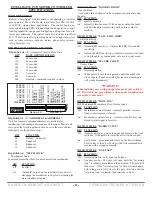
Dip Switch A1 – 3:
Automatic Timer to Close Gate
DIP
GATE OPEN DURATION
111
60 seconds
110
45 seconds
101
30 seconds
100
15 seconds
011
10 seconds
010
5 seconds
001
0 seconds
000
disabled – command required to close
Dip Switch A4 – 5: “ADDRESS 1 & ADDRESS 0”
Up to four separate entrance addresses are available for
installations with multiple entrance or exit locations. Master and
slave gates that work together should be set to the same address.
(Side gates use the address setup)
DIP
FUNCTION
00
Default – Entrance 1
01
Entrance 2
10
Entrance 3
11
Entrance 4
Dip Switch A6: “MECH. LOCK”
Mechanical Lock
For motor assemblies that use a mechanical lock mechanism.
DIP
FUNCTION
‘off’
no effect
‘on’
“Solenoid” output, on the terminal strip is used to
disengage the mechanical lock prior to actuating the
motor in either direction.
DIP SWITCH A7: “DOOR-IN-DOOR”
Door-In-Door
Used with a three button switch or a pedestrian entranceto stop
the gate.
DIP FUNCTION
‘off’ normal operation
‘on’ normally closed contact. With an open contact the board
will stop the gate from moving until a close contact is
reached.
DIP SWITCH A8: “LOW - ERD - HIGH”
ERD Sensitivity
DIP FUNCTION
‘off’ Normal ERD sensitivity – Adjusts the ERD for standard
sensitivity.
‘on’ Adjusts the ERD sensitivity so that more pressure is needed
to stop the gate.
(recommended: only use in windy areas)
DIP SWITCH B1: “SECURE CLOSE”
Secure Close
DIP FUNCTION
‘off’ Normal operation
‘on’
When power is lost, then regained, control board checks
status of gate. If open and safety devices are cleared, gate
will close automatically.
*WARNING*
When installing or servicing an operator, make sure switch is
off. If switch is ‘on’ gate will move when power is applied and
severe injury may occur.
DIP SWITCH B2: “MOM. SOS”
SOS Maintained/Momentary (Uses Firebox input)
DIP
FUNCTION
‘off’ Maintained contact closure – normal operation, releases
when contact closure is cleared.
‘on’
Momentary contact closure – releases only after a second
closed contact signal is received.
DIP SWITCH B3: “RADIO CYCLE”
DIP
FUNCTION
‘off’ Normal operation – gate only opens and closes on the limit
switches. If the gate is in travel then it will always open.
‘on’
Cycle mode – gate opens and closes on the limit switches,
but if in travel, then it will stop with a first command and
reverse with a second command.
DIP SWITCH B4: “ONE PASS”
DIP FUNCTION
‘off’ Normal operation - fully opens and closes
‘on’ One pass mode - The gate will open until the "reversing
loop" is initially activated and then cleared. The gate will
then close. If the "reversing loop" is then activated again,
before the gate is fully closed, the gate will stop until the
"reversing loop" is cleared, then continue to close.
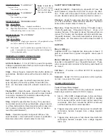
ADDRESS 1 ADDRESS 0 MECH LOCK DOOR-IN-DOOR LOW-ERD-HIGH
SECURE CLOSE MOM. SOS RADIO CYCLE ONE PASS LAG DELAY LAG MODE REVERSE LOGIC SLAVE MODE
ON
Î
1 2 3 4 5 6 7 8
Dip Switch “A”
Dip Switch “B”
60 SECS 1 1 1
45 SECS 1 1 0
30 SECS 1 0 1
15 SECS 1 0 0
10 SECS 0 1 1
5 SECS 0 1 0
0 SECS 0 0 1
DISABLED 0 0 0
Figure 9
1 2 3 4 5 6 7 8


