


R A M S E T
z
R A M S E T
z
R A M S E T
RA
MS
ET
z
RA
MS
ET
z
RA
MS
ET
- 1 -
TABLE OF CONTENTS
Important Safety Requirements & Instructions . . . . . . . . . . . . . . . . . . . . . . . . . . . . . . . . . . . . . . .1,2
Mechanical Specifications . . . . . . . . . . . . . . . . . . . . . . . . . . . . . . . . . . . . . . . . . . . . . . . . . . . . . .3
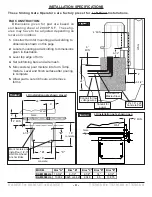
Installation Specifications . . . . . . . . . . . . . . . . . . . . . . . . . . . . . . . . . . . . . . . . . . . . . . . . . . . . . . .4
Pad Construction . . . . . . . . . . . . . . . . . . . . . . . . . . . . . . . . . . . . . . . . . . . . . . . . . . . . . . . . . . . . .4
Recommended Wire Gauge / Voltage Drop Chart . . . . . . . . . . . . . . . . . . . . . . . . . . . . . . . . . . . .5
Gate Travel Adjustment . . . . . . . . . . . . . . . . . . . . . . . . . . . . . . . . . . . . . . . . . . . . . . . . . . . . . . . .6
Pushbutton Controls . . . . . . . . . . . . . . . . . . . . . . . . . . . . . . . . . . . . . . . . . . . . . . . . . . . . . . . . . . .6
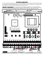
Electrical Connection . . . . . . . . . . . . . . . . . . . . . . . . . . . . . . . . . . . . . . . . . . . . . . . . . . . . . . . . . .7
INTELLIGATE PCB MOTOR CONTROLLER SPECIFICATION
Introduction . . . . . . . . . . . . . . . . . . . . . . . . . . . . . . . . . . . . . . . . . . . . . . . . . . . . . . . . . . . . . .8
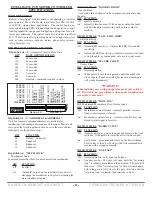
DIP Switch Configurations . . . . . . . . . . . . . . . . . . . . . . . . . . . . . . . . . . . . . . . . . . . . . . . . . . .8,9
TERMINAL STRIP CONNECTIONS . . . . . . . . . . . . . . . . . . . . . . . . . . . . . . . . . . . . . . . . . . .9
Wiring Diagram . . . . . . . . . . . . . . . . . . . . . . . . . . . . . . . . . . . . . . . . . . . . . . . . . . . . . . . . . . . . . .10
Sensor Installation . . . . . . . . . . . . . . . . . . . . . . . . . . . . . . . . . . . . . . . . . . . . . . . . . . . . . . . . . . . .11
Master - Slave Installation . . . . . . . . . . . . . . . . . . . . . . . . . . . . . . . . . . . . . . . . . . . . . . . . . . . . . .11
Bill of Materials . . . . . . . . . . . . . . . . . . . . . . . . . . . . . . . . . . . . . . . . . . . . . . . . . . . . . . . . . . . . . . .12
RAM-1000 UL Parts Diagram . . . . . . . . . . . . . . . . . . . . . . . . . . . . . . . . . . . . . . . . . . . . . . . . . . . .13
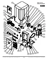
RAM-5500 UL Parts Diagram . . . . . . . . . . . . . . . . . . . . . . . . . . . . . . . . . . . . . . . . . . . . . . . . . . . .14
Glossary . . . . . . . . . . . . . . . . . . . . . . . . . . . . . . . . . . . . . . . . . . . . . . . . . . . . . . . . . . . . . . . . . . . .15
IMPORTANT SAFETY REQUIREMENTS & INSTRUCTIONS
WARNING - To reduce the risk of injury or death:
1. READ AND FOLLOW ALL INSTRUCTIONS.
2.
Never let children operate or play with gate
controls. Keep the remote control away from
children.
3.
Always keep people and objects away from
the gate. NO ONE SHOULD CROSS THE
PATH OF THE MOVING GATE.
4.
Test the Vehicular Gate Operator monthly. The
gate MUST reverse on contact with a rigid
object or stop when an object activates the
non-contact sensors. After adjusting the limit
of travel, retest the Vehicular Gate Operator.
Failure to adjust and retest the Vehicular Gate
Operator properly can increase the risk of
injury or death.
5.
Use the Emergency Release only when power
switch or circuit breaker has been turned off.
Using the Emergency Release during a power
failure can be a hazard if power is abruptly
restored.
6.
KEEP GATES PROPERLY MAINTAINED.
Read the Owner's Manual. Have a qualified
service person make repairs to gate hardware.
7.
The entrance is for vehicles only. Pedestrians
must use separate entrance.
8.
SAVE THESE INSTRUCTIONS.
NOTE: Always consult and follow all local building and electrical codes prior to installation.
Ramset Gate Operators should not be installed without non-contact sensing devices such as non-con-
tact sensors, photo electric sensors or the equivalent.
n
WARNING
A non-contact sensor (photoelectric sensor or equivalent) and a contact sensor (edge
device or equivalent) is required on each individual installation to comply with UL325.
Reversing Sensors (Loop Detectors)
Reversing Sensors should be used to prevent gate from closing when a vehicle is in the gate area.