R A M S E T
z
R A M S E T
z
R A M S E T
RA
MS
ET
z
RA
MS
ET
z
RA
MS
ET
- 9 -
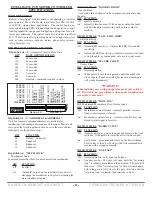
DIP SWITCH B5: “LAG DELAY”
Lag on Close
One second lag on close
DIP SWITCH B6: “LAG MODE”
Lag on Open
One second lag on open
DIP SWITCH B7: “REVERSE LOGIC”
DIP FUNCTION
‘off’ Left hand operation – standard installation
‘on’ Right hand installations – Reverses motor & limit switches
without having to move any wires.
DIP SWITCH B8: “SLAVE MODE”
Master/slave
DIP FUNCTION
‘off’ Master mode – single gate operation. All peripheral devices
are to be connected to the master operator.
‘on’ Slave mode – used to synchronize operation between two
gates. Commands are received from the master through a
3-wire, shielded cable.
TERMINAL STRIP CONNECTIONS
CONTROL INPUT DESCRIPTIONS
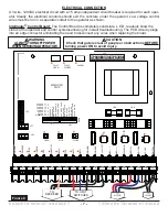
AC Hot & Neutral
– 110 or 220 VAC to power the operator.
Voltage is predetermined at factory and cannot be changed
by the installer or technician.
Close
– Closes the gate. Used with three button stations or
pushbuttons. Becomes active with a closed contact to com-
mon.
Exit
– Opens the gate. Used with loop detectors, photo
eyes, keypads, phone entry systems, three-button sta-
tions…etc. Becomes active with a closed contact to com-
mon.
Firebox/SOS
– Opens the gate. Used with fire dept. key
switches & controls. Becomes active with a closed contact
to common, maintained or momentary depending on dip
switch B2 (see “dip switch features”).
Stop
– Stops the operator from moving. To be used as a
non-contact sensor such as a photo-beam, edge connector
or a three-button station. Becomes active with an open con-
tact to common when dip switch A7 is in the ‘on’ position
(see “dip switch features”).
Radio
– Operation depends on dip switch B3 (see “dip
switch features”). Used with an RF receiver or pushbutton.
Becomes active with a closed contact to common.
SAFETY INPUT DESCRIPTION
Limit 1 & Limit 2
– Depending on dip switch B7 (see “dip
switch features”), stops the motor from moving in one direc-
tion. These wires are preset in factory and should not be
moved. Becomes active with a closed contact to common.
Phantom
– Keeps the gate open when the open limit switch
(A or B) is activated. Used with loop detectors. Becomes
active with a closed contact to common.
Rev Loop
– Stops the gate from closing. If the gate is open,
it holds the gate open. If the gate is closing, it stops and
reopens the gate. If the gate is closed, the gate will remain
closed. The function can be altered with dip switch B4 (see
“dip switch features”). Used with loop detectors, photo eyes,
safety edges…etc. Becomes active with a closed contact to
common.
OUTPUTS
Mag
(
+
)
& Mag
(
-
)
Supplies 24VDC to a magnetic lock when gate is closed. If
gate is not closed then no power is supplied. Leave open if
not used.
Motor 1 & Motor 2
– Supplies power to the motor. Direction
depends on dip switch B7 (see “dip switch features”). These
wires are preset and connected in the factory and should not
be moved.
24V Rect.
– Provides a rectified 24VDC for peripheral
accessories.
Solenoid
– Sends 110 VAC to a solenoid or other mechani-
cal lock. Leave open if not used.
OTHER CONNECTIONS
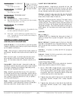
Contact Closure Relay Outputs
Three separate isolated form-C relay outputs are provided.
Each relays contact is rated at 125VAC, 2 amps.
1.
Alarm – When ERD is triggered twice, before reaching a
fully closed or fully opened position, 24VDC is supplied
for 6 minutes and the control board will not accept any
commands. After the 6 minutes the 24VDC is removed
and the board resets to normal operation.
2.
Triggers relay when gate is fully opened. Used with indi-
cator lights, buzzers, beepers, misc. voltage magnetic
locks…etc.
3.
Triggers relay when gate is fully closed. Used with indi-
cator lights, buzzers, beepers, misc. voltage magnetic
locks…etc.
Note
: if both B5 &
B6 are 'on', there
will be NO lag on
the open or close.


