


Weather Station - Model “PRO”
Model “PRO” - Weather Station
Page
49
Nov., 2001
GT27145B Cozz
of corrosion build up on the switch
over time.
•
The reed switch is easily replaced
and the parts are available from your
local Rain Bird Distributor.
TEMPERATURE AND
RELATIVE HUMIDITY SENSOR
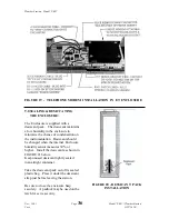
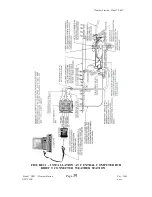
Refer to schematic wiring diagram -
located in the Appendix - FIGURE 32
•
Set the meter to DC volts and check
across pins #4 & #6 for 12VDC.
DO NOT
connect an OHM meter across
the RH chip or damage may occur to the
RH chip. If you are experiencing
problems with the temperature and
relative humidity probe - determine the
following:
•
Are both the temperature and
humidity readings “bad” ?
•
Is just the temperature reading
“bad”?
•
Is the RH reading “bad” ?
•
If just the RH readings are “bad” -
then the RH chip most likely needs
to be replaced. New RH chips, for
replacement, are available from your
local Rain Bird Distributor.
AIR TEMPERATURE PROBE
( ON REDUCED SET STATION
ONLY )
Refer to schematic wiring diagram -
located in the Appendix - FIGURE 33
•
Set meter to OHMs and measure
from E1 to 1H (pins #3 to #1) should
read a minimum of 249K OHMS.
Colder temperatures result in higher
resistances.
•
With meter on OHMS measure from
1H to AG (pins #1 to #5). Should
have a fixed reading of 1K OHMS
resistance.
•
With meter on OHMS measure from
E1 to 1L (pins #3 to #2) should read
a minimum of 249K OHMS.
Colder temperatures result in higher
resistances.
•
With meter on OHMS measure from
1L to AG (pins #2 to #5). Should
have a fixed reading of 1K OHMS
resistance.
TROUBLESHOOTING:
The following information is for trouble-
shooting the weather station only.


