


Programming and Operation,
continued
38
Example:
If your system uses 100 FD102TURF Field
Decoders (each operating one solenoid output), then
test results should show a
Before
reading of about
50 mA,
Inrush
of 525 mA (which is within the 290-
700 range), and a
hold
of 70 mA (which is 20 mA
higher than the
Before
reading).
Note:
If the
Before
,
Inrush
and
hold
values are
close, the decoder is not responding. Locate the
decoder in the field and make sure that it is wired
properly to the solenoid and communications cable.
You should also make sure you programmed in the
right
Decoder Addresses (REC . NO .)
.
5. Press the button pointing to the
OK
label
twice
to activate and test the next decoder in line.
6. The
minus (-)
label cancels the
test
at any time,
returning to the
Test
menu.
Note:
To set up the MDC2 Controller to
automatically activate and test each decoder in
sequence, please see
Setting Up an Automatic
Test Program
on page 48.
Testing the Sensor Decoders
Once you install and program the sensor decoders
into your system, you can then test to make sure
they are working properly. The MDC2 Controller
has a built-in sensor decoder test that enables you
to test each sensor decoder.
1. From the
Main Menu
, select
4. Test
and select
OK
.
The
Test Menu
screen appears.
2. Select
2. Test of Sensor Decoders
and select
OK
.
The
Test of Sensor Decoders
screen appears.
3. Use the
up
and
down
arrows
to choose the
sensor decoder to be tested and select
OK
.
The “
Communicating with the SD, please
wait
” message appears.
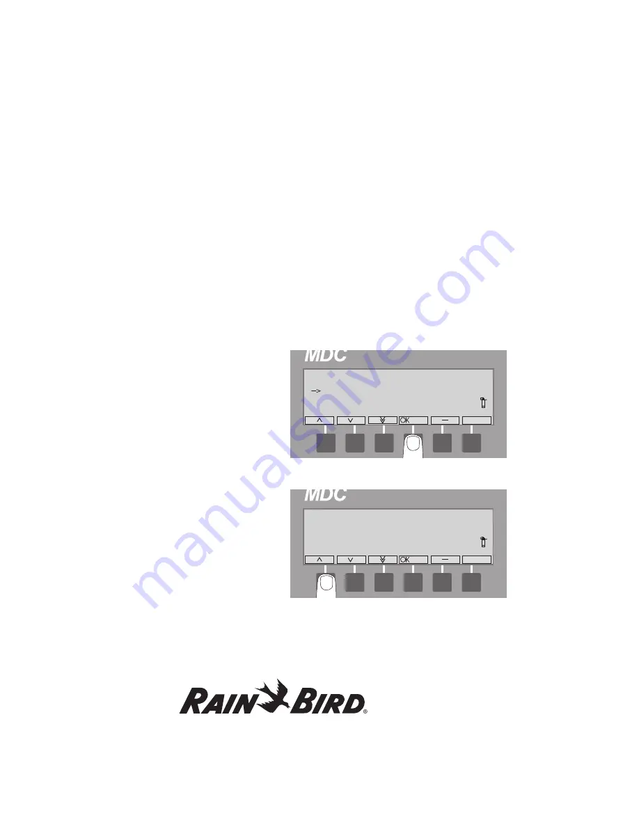
*** Test Menu ***
01:36 PM
1. Test of Line Decoders
2. Test of Sensor Decoders
3. Short Finding
4. Line Surv
5. Return
*** Test of Sensor Decoders ***
No Sensor Decoders are Installed!
Press OK or ‘ ’ to continue
–
*** Test of Sensor Decoders ***
01:37 PM
Sensor Decoder: SD1 50085
‘OK’ run test, ‘ for exit
or Up/Down for Prev/Next.
–’
Summary of Contents for MDC2
Page 1: ...MDC Controller Unit MDC2...
Page 10: ......
Page 82: ...This page intentionally left blank...
Page 98: ...This page intentionally left blank...
Page 114: ...This page intentionally left blank...
Page 122: ...This page intentionally left blank...