Programming and Operation,
continued
31
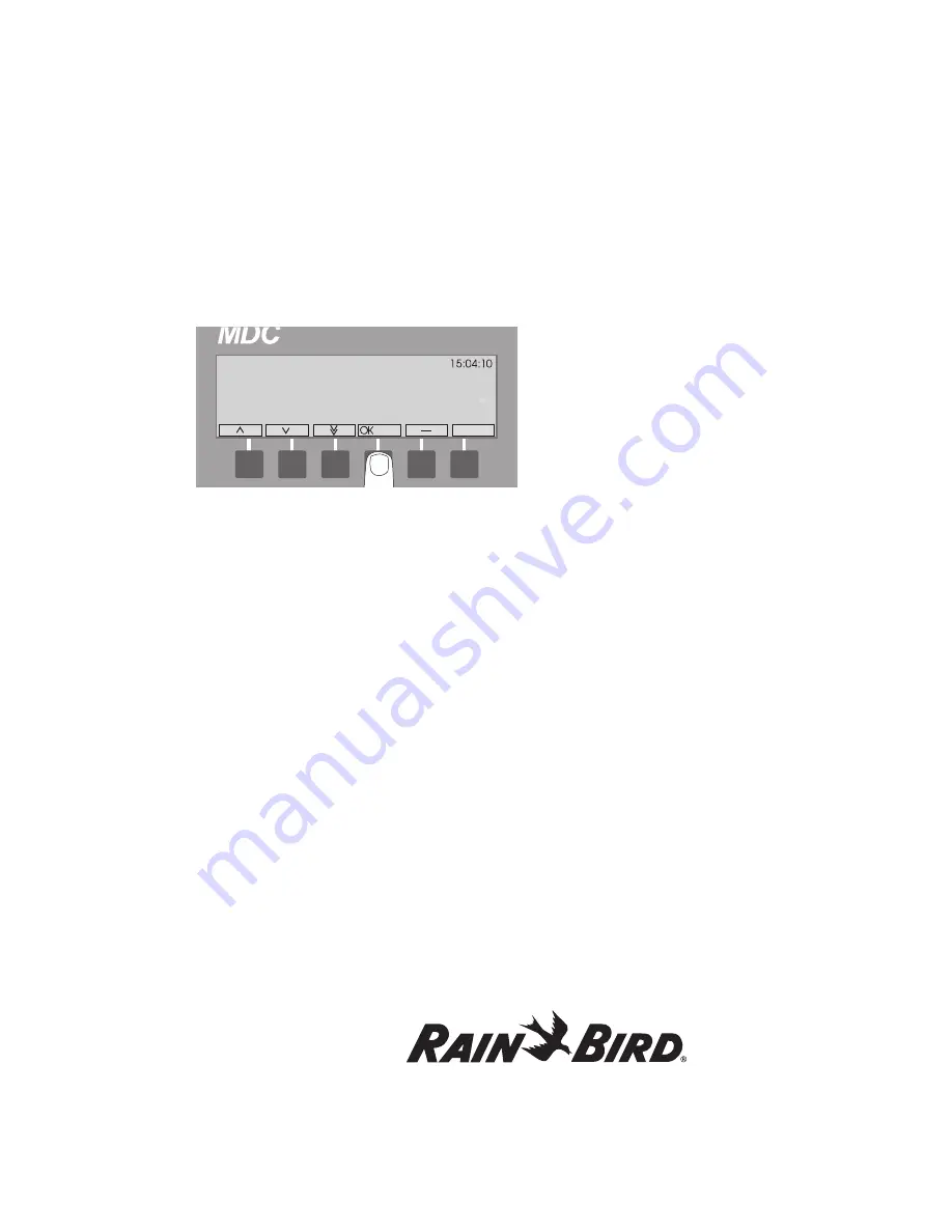
4. Select
OK
and the blinking
markers
are
positioned under
Name
.
5. Select
OK
to activate the
Name
field. Use the
up
and
down arrows
to change the default decoder
name. Select
OK
to store the name.
You will notice that the
up
and
down arrows
switch to the
left
and
right arrows
to facilitate
the navigation through the configuration
parameters.
6. Move the markers to the
Type
field and activate.
Use the
up
and
down arrows
to set the decoder
type and select
OK
to save it.
Note
: For
Flow Sensor Decoders
,
Flow Definition
allows you to program a Rain Bird
®
SD-210TURF
Sensor Decoder to the type of flow sensor your
system uses - either digital (pulse output) or analog
(4-20 milliamps). To establish a conversion ratio, the
controller uses to calculate the flow, you only need
to program the flow output and sensor output.
Rain Bird
®
recommends you enter the maximum
flow, which determines the pulse type.
Note
:
Digital
(pulse output) flow sensors are
most common. Please see the manufacturers’
specifications to determine the
sensor type,
maximum flow
and
sensor output
.
7. Move the markers to the
Address
field and
activate. Use the
up
and
down arrows
to set the
decoder address and select
OK
to save it.
8. Move the markers to the
@
field and activate.
Use the
up
and
down arrows
to set the
@
value
and select
OK
to save it.
9. Move the markers to the
value
field and
activate. Use the
up
and
down arrows
to set the
value and select
OK
to save it.
10. Move the markers to the
Units
field and activate.
Use the
up
and
down arrows
to choose the
units and select
OK
to save it.
Note
: Choose
Pulse/10s
if your
digital
flow sensor
uses a higher pulse rate (30-200 pulses per second)
and counts the number of pulses in 10-second
intervals. Choose
mA
if you are using an analog flow
sensor.
11. Move the markers to the
Sum
field and activate.
Use the
up
and
down arrows
to choose either
Yes
or
No
and select
OK
to save it.
Now, it is time to define the
alarm conditions
.
This feature allows you to set specific
alarm
limits
when the controller is in the
Auto
mode.
Once input from the sensor decoder goes
beyond the set limit (which can occur if a valve
opens to a broken pipe), the controller turns off
all active decoders, displays and logs an alarm.
Note:
For
Flow Control
set as below condition
and alarms management the following should be
considered:
1. When the flow has a transition from a value above
the limit to below an alarm will trigger.
2. If no decoders are running for a period of time the
MDC will be in non-irrigation mode and thus look
for leak flow if set up to do so.
** Sensor Decoder Set-up **
Name Type Addr. @ Val Units Sum
>SD1< Flow 50000 20 100 mA NA
Alarm Cond. Limit Action Obj. Obj. ID
1. NA 100 Deact Decod All
2. Below 12 Deact Decod All
Summary of Contents for MDC2
Page 1: ...MDC Controller Unit MDC2...
Page 10: ......
Page 82: ...This page intentionally left blank...
Page 98: ...This page intentionally left blank...
Page 114: ...This page intentionally left blank...
Page 122: ...This page intentionally left blank...


