


4-16
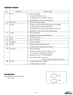
Inspecting Air Compressor
Inspecting Air Compressor
Inspecting Air Compressor
Inspecting Air Compressor
No.
Component
Points to check
Piston
•
Wear and damage
•
Check outer diameter of piston
•
Connecting rod : Confirm smooth operation
•
Big end bearing : Confirm smooth operation
Piston ring
•
Measure piston ring end gap
Bearing
•
Rotate by hand and check for excessive play and catching
•
Replace with new one if defects are found
•
Be careful not to scratch housing when removing bearing
•
Apply force to outer race when press fitting bearing
Oil seal
•
Wear and damage
•
Replace with new one if defects are found
0-ring
•
Scratches and wear
Collar
•
Wear and damage
Crankshaft
•
Wear and damage
Cylinder
•
Sliding surface of piston for scratches
•
Correct or replace if problems are detected
Reed valve
•
Wear and damage
•
Reed valve clearance: 0.2 mm (0.008 in) or less
•
Correct or replace if problems are detected
•
Reed valve stopper
③- -
Wear and damage
③- Valve stopper height: 2 mm (0.08 in)
-③Correct or replace if problems are detected
Air filter
•
Confirm whether dirty or clogged
•
Replace with new one if dirty
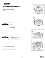
Assembling Piston
Assembling Piston
Assembling Piston
Assembling Piston
Assemble the following components.
•
Piston rings
Summary of Contents for 40 hp
Page 3: ......
Page 9: ...1 2 2 O 2 O 2 O 2 Outline Dimensions utline Dimensions utline Dimensions utline Dimensions ...
Page 17: ...1 10 ...
Page 19: ...2 2 ...
Page 20: ...2 1 ...
Page 35: ...2 16 5 Special Tools 5 Special Tools 5 Special Tools 5 Special Tools ...
Page 43: ...2 24 ...
Page 48: ...3 5 ...
Page 50: ...3 7 ...
Page 54: ...3 11 ...
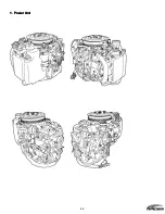
Page 57: ...4 2 1 1 1 1 Power Uni Power Uni Power Uni Power Unit t t t ...
Page 60: ...4 5 ...
Page 66: ...4 11 ...
Page 68: ...4 13 ...
Page 72: ...4 17 ...
Page 75: ...4 20 ...
Page 86: ...4 31 ...
Page 97: ...4 42 Piston and Crankshaft Piston and Crankshaft Piston and Crankshaft Piston and Crankshaft ...
Page 106: ...4 51 ...
Page 111: ...5 2 1 1 1 1 Wire Routing Wire Routing Wire Routing Wire Routing ...
Page 112: ...5 3 ...
Page 113: ...5 4 ...
Page 114: ...5 5 ...
Page 115: ...5 6 ...
Page 116: ...5 7 Wiring Diagram 40B 50B EPTO ...
Page 117: ...5 8 ...
Page 118: ...5 9 ...
Page 119: ...5 10 ...
Page 120: ...5 11 ...
Page 121: ...5 12 ...
Page 126: ...5 17 Note Slash shows stripe color of cable 2 2 2 2 Assembly Assembly Assembly Assembly ...
Page 127: ...5 18 Wiring around solenoid Bracket ...
Page 128: ...5 19 ...
Page 129: ...5 20 ...
Page 130: ...5 21 ...
Page 136: ...5 27 Kill Switch Crank Sensor Oil Level Sensor Grounds Air Injector 1 ...
Page 137: ...5 28 Air Injector 2 Air Injector 3 Coil 1 Coil 2 Coil 3 ...
Page 138: ...5 29 Fuel Pump Fuse Box Regulator Stator Complete Wiring harness ...
Page 140: ...6 2 1 1 1 1 Configuration Configuration Configuration Configuration GEARCASE DRIVESHAFT ...
Page 141: ...6 3 GEARCASE PROPELLERSHAFT ...
Page 152: ...6 14 ...
Page 153: ...6 15 ...
Page 185: ...10 20 ...
Page 193: ...11 8 ...