


10-7
1.
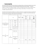
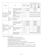
Troubleshooting Table
Troubleshooting Table
Troubleshooting Table
Troubleshooting Table
Thissectionontroubleshootingcoversthevariousmalfunctionsandfailuresthatcanoccurintheengine'selectr
i
calcomponents.Not
ificationofmalfunctionsandfailuresisprovidedusingasystemofwarningbeep(buzzer)andindicatorlights
. The Raider is
prepared for a mission prior to placing on the RIB. The outboard is designed that only two of the three cylinders need to
work to get home. The key parameter the operator must continually visually checking is to insure water is being
continually coming from the outboard.
This Raider Outboard has silenced all alarms to avoid mission compromise. The signals and warnings are recorded in the
Electronics Control Unit that can be downloaded at the maintenance shop. The Raider on the mission should have fuel
and oil reserve full. Emergency get home support is found in the BII kit.
Item
Self-diagnosable
points
Beeps
Disabled
Warning
Disabled
Warning
Disabled
Warning
Disabled
1-1.
Gearshift
1-2.
Battery
0
Flashing
1-3.
Fuse
1-4.
Wiring
1
.
Starter motor dead
Or turns
very slowly Only on Raiders
when ordered
1-5.
Electrical components
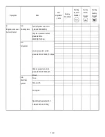
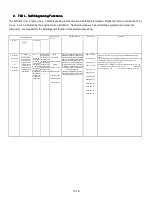
2-1.
Powerhead
Insufficient compression
Bladder/Fuel tank
0
Flashing
Flashing
Flash
i
ng
2.
Engine turns over but won’t
start
2-2.
Fuel system
Low fuel pressure in air
rail
[standard:600to640kPa]
87to 93 ps
i
Summary of Contents for 40 hp
Page 3: ......
Page 9: ...1 2 2 O 2 O 2 O 2 Outline Dimensions utline Dimensions utline Dimensions utline Dimensions ...
Page 17: ...1 10 ...
Page 19: ...2 2 ...
Page 20: ...2 1 ...
Page 35: ...2 16 5 Special Tools 5 Special Tools 5 Special Tools 5 Special Tools ...
Page 43: ...2 24 ...
Page 48: ...3 5 ...
Page 50: ...3 7 ...
Page 54: ...3 11 ...
Page 57: ...4 2 1 1 1 1 Power Uni Power Uni Power Uni Power Unit t t t ...
Page 60: ...4 5 ...
Page 66: ...4 11 ...
Page 68: ...4 13 ...
Page 72: ...4 17 ...
Page 75: ...4 20 ...
Page 86: ...4 31 ...
Page 97: ...4 42 Piston and Crankshaft Piston and Crankshaft Piston and Crankshaft Piston and Crankshaft ...
Page 106: ...4 51 ...
Page 111: ...5 2 1 1 1 1 Wire Routing Wire Routing Wire Routing Wire Routing ...
Page 112: ...5 3 ...
Page 113: ...5 4 ...
Page 114: ...5 5 ...
Page 115: ...5 6 ...
Page 116: ...5 7 Wiring Diagram 40B 50B EPTO ...
Page 117: ...5 8 ...
Page 118: ...5 9 ...
Page 119: ...5 10 ...
Page 120: ...5 11 ...
Page 121: ...5 12 ...
Page 126: ...5 17 Note Slash shows stripe color of cable 2 2 2 2 Assembly Assembly Assembly Assembly ...
Page 127: ...5 18 Wiring around solenoid Bracket ...
Page 128: ...5 19 ...
Page 129: ...5 20 ...
Page 130: ...5 21 ...
Page 136: ...5 27 Kill Switch Crank Sensor Oil Level Sensor Grounds Air Injector 1 ...
Page 137: ...5 28 Air Injector 2 Air Injector 3 Coil 1 Coil 2 Coil 3 ...
Page 138: ...5 29 Fuel Pump Fuse Box Regulator Stator Complete Wiring harness ...
Page 140: ...6 2 1 1 1 1 Configuration Configuration Configuration Configuration GEARCASE DRIVESHAFT ...
Page 141: ...6 3 GEARCASE PROPELLERSHAFT ...
Page 152: ...6 14 ...
Page 153: ...6 15 ...
Page 185: ...10 20 ...
Page 193: ...11 8 ...