


7-7
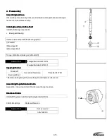
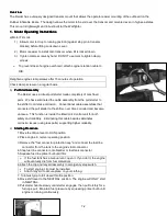
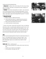
The Raider has three starting modes.
1. Battery Start
Battery Start
Battery Start
Battery Start - the battery located under cowling, this is the primary starting
mode. If the battery is dead use the conventional pull start..The battery will
recharge very quickly.
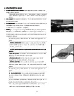
2. Pull Start
Pull Start
Pull Start
Pull Start- The secondary starting method is the Raider. If your motor does
not come with a battery this option is the primary starting method. The pull
start has been designed for rough use and should not fail. The most frequent
failure is rope failure or weapon fire that might affect the pull start.*In event of
damage proceed to step 3.
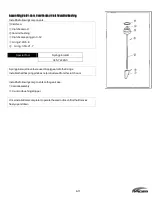
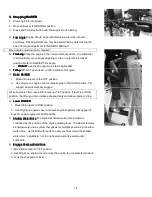
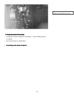
3. Emergency Pull Start
. Emergency Pull Start
. Emergency Pull Start
. Emergency Pull Start -
a)
Remove Cowling by unlatching the cowling.
b)
Open the Basic Issue Items kit. A special service tool (wrench) is
contained that fits the bolts holding the pull starter to the flywheel.
c)
Remove bolts and the starter can be removed.
d)
Lift starter assembly from Raider engine.
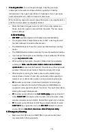
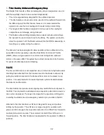
*If starter cord is broken, it might not be long enough to use as an emergency
starter cord. If intact, cut cord from starter assembly, tie knot in the end. If this
rope is inadequate you will find in the Basic Issue Items (BII) is a rope. Tie a
knot in the end of the rope, Insert the knot end of rope into the flywheel notch;
wrap rope around flywheel clockwise; tighten rope until pressure is felt, pull
hard on the wooden handle with a quick solid motion to start the Raider.
Note:
Note:
Note:
Note:
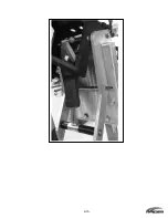
You can open the dewatering unit for a first pull to insure the motor turns over
freely. The dewatering valves will act as a compression release. Close
dewatering valve to start after determining the outboard pulls over freely.
After starting replace engine cover; put aside the pull starter for further
maintenance.
Engine cover:
Engine cover:
Engine cover:
Engine cover: This is a machinery guard.
o
Prevent injury by keeping hands, clothing, and hair clear of all moving
parts.
o
DO NOT use your hands to turn the flywheel;
o
use recoil starter or emergency rope only.
Summary of Contents for 40 hp
Page 3: ......
Page 9: ...1 2 2 O 2 O 2 O 2 Outline Dimensions utline Dimensions utline Dimensions utline Dimensions ...
Page 17: ...1 10 ...
Page 19: ...2 2 ...
Page 20: ...2 1 ...
Page 35: ...2 16 5 Special Tools 5 Special Tools 5 Special Tools 5 Special Tools ...
Page 43: ...2 24 ...
Page 48: ...3 5 ...
Page 50: ...3 7 ...
Page 54: ...3 11 ...
Page 57: ...4 2 1 1 1 1 Power Uni Power Uni Power Uni Power Unit t t t ...
Page 60: ...4 5 ...
Page 66: ...4 11 ...
Page 68: ...4 13 ...
Page 72: ...4 17 ...
Page 75: ...4 20 ...
Page 86: ...4 31 ...
Page 97: ...4 42 Piston and Crankshaft Piston and Crankshaft Piston and Crankshaft Piston and Crankshaft ...
Page 106: ...4 51 ...
Page 111: ...5 2 1 1 1 1 Wire Routing Wire Routing Wire Routing Wire Routing ...
Page 112: ...5 3 ...
Page 113: ...5 4 ...
Page 114: ...5 5 ...
Page 115: ...5 6 ...
Page 116: ...5 7 Wiring Diagram 40B 50B EPTO ...
Page 117: ...5 8 ...
Page 118: ...5 9 ...
Page 119: ...5 10 ...
Page 120: ...5 11 ...
Page 121: ...5 12 ...
Page 126: ...5 17 Note Slash shows stripe color of cable 2 2 2 2 Assembly Assembly Assembly Assembly ...
Page 127: ...5 18 Wiring around solenoid Bracket ...
Page 128: ...5 19 ...
Page 129: ...5 20 ...
Page 130: ...5 21 ...
Page 136: ...5 27 Kill Switch Crank Sensor Oil Level Sensor Grounds Air Injector 1 ...
Page 137: ...5 28 Air Injector 2 Air Injector 3 Coil 1 Coil 2 Coil 3 ...
Page 138: ...5 29 Fuel Pump Fuse Box Regulator Stator Complete Wiring harness ...
Page 140: ...6 2 1 1 1 1 Configuration Configuration Configuration Configuration GEARCASE DRIVESHAFT ...
Page 141: ...6 3 GEARCASE PROPELLERSHAFT ...
Page 152: ...6 14 ...
Page 153: ...6 15 ...
Page 185: ...10 20 ...
Page 193: ...11 8 ...