


3-4
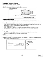
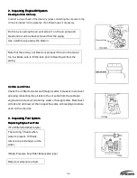
Cleaning Bladder/Fuel Tank Filter
Cleaning Bladder/Fuel Tank Filter
Cleaning Bladder/Fuel Tank Filter
Cleaning Bladder/Fuel Tank Filter
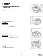
Fuel pickup elbow
Filter
Turn to the left to remove and clean .
Cleaning Bladder/Fuel Tank
Cleaning Bladder/Fuel Tank
Cleaning Bladder/Fuel Tank
Cleaning Bladder/Fuel Tank.(Not supplied with RAIDER )
.(Not supplied with RAIDER )
.(Not supplied with RAIDER )
.(Not supplied with RAIDER )
Clean the bladder/fuel tank whenever there is a buildup of water or
foreign matter.
1.
1.
1.
1.
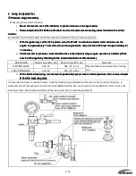
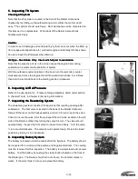
Inspecting Compression System
Inspecting Compression System
Inspecting Compression System
Inspecting Compression System
Measuring Procedures
Measuring Procedures
Measuring Procedures
Measuring Procedures
Use the following procedures to measure the compression of the
individual cylinders.
1.
Fully charge the engine battery (optional).
2.
Start engine and idle for 3 minutes to warm.
3.
Unlock the stop switch.
4.
Remove all spark plugs.
5.
Remove all air injector and fuel injector connectors.
Accurate compression readings are only possible when all & connectors
are disconnected. It should also be noted that the ECU records detailed
information on which connectors were disconnected during each inspection.
Refer to the section on the TLDI self-diagnosing function for more information.
6.
Attach the compression gauge into the sparkplug hole (only one at a
time).
7.
Use the starter motor to turn over the engine.
Engine speed: approx. 400 rpm for at least 5 seconds
(Note that throttle position does not affect compression
readings.)
•
Measure the compression for all cylinders
•
Confirm that all compression readings conform to specifications.
Rated compression:
830 kPa (8.5 kg/cm
2
, 120 psi)
④10%
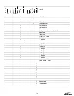
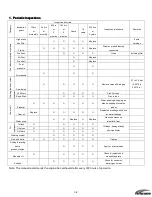
Results and Steps to Take
Results and Steps to Take
Results and Steps to Take
Results and Steps to Take
Repair or replace components as necessary when the readings fall under the
following categories.
•
Below specified compression:
•
Difference between cylinders
exceeds 103 kPa (1.05
kg/cm
2
, 15 psi)
•
Compression is abnormally
high.
Summary of Contents for 40 hp
Page 3: ......
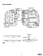
Page 9: ...1 2 2 O 2 O 2 O 2 Outline Dimensions utline Dimensions utline Dimensions utline Dimensions ...
Page 17: ...1 10 ...
Page 19: ...2 2 ...
Page 20: ...2 1 ...
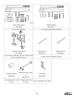
Page 35: ...2 16 5 Special Tools 5 Special Tools 5 Special Tools 5 Special Tools ...
Page 43: ...2 24 ...
Page 48: ...3 5 ...
Page 50: ...3 7 ...
Page 54: ...3 11 ...
Page 57: ...4 2 1 1 1 1 Power Uni Power Uni Power Uni Power Unit t t t ...
Page 60: ...4 5 ...
Page 66: ...4 11 ...
Page 68: ...4 13 ...
Page 72: ...4 17 ...
Page 75: ...4 20 ...
Page 86: ...4 31 ...
Page 97: ...4 42 Piston and Crankshaft Piston and Crankshaft Piston and Crankshaft Piston and Crankshaft ...
Page 106: ...4 51 ...
Page 111: ...5 2 1 1 1 1 Wire Routing Wire Routing Wire Routing Wire Routing ...
Page 112: ...5 3 ...
Page 113: ...5 4 ...
Page 114: ...5 5 ...
Page 115: ...5 6 ...
Page 116: ...5 7 Wiring Diagram 40B 50B EPTO ...
Page 117: ...5 8 ...
Page 118: ...5 9 ...
Page 119: ...5 10 ...
Page 120: ...5 11 ...
Page 121: ...5 12 ...
Page 126: ...5 17 Note Slash shows stripe color of cable 2 2 2 2 Assembly Assembly Assembly Assembly ...
Page 127: ...5 18 Wiring around solenoid Bracket ...
Page 128: ...5 19 ...
Page 129: ...5 20 ...
Page 130: ...5 21 ...
Page 136: ...5 27 Kill Switch Crank Sensor Oil Level Sensor Grounds Air Injector 1 ...
Page 137: ...5 28 Air Injector 2 Air Injector 3 Coil 1 Coil 2 Coil 3 ...
Page 138: ...5 29 Fuel Pump Fuse Box Regulator Stator Complete Wiring harness ...
Page 140: ...6 2 1 1 1 1 Configuration Configuration Configuration Configuration GEARCASE DRIVESHAFT ...
Page 141: ...6 3 GEARCASE PROPELLERSHAFT ...
Page 152: ...6 14 ...
Page 153: ...6 15 ...
Page 185: ...10 20 ...
Page 193: ...11 8 ...