


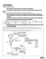


2-7
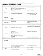
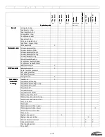
Name of Part
Item to check
Standard values
Manual Trim and Tilt
Tilt Cylinder
•
19600 to 24500 kPa
Air Compressor
•
Cylinder bore
•
Piston diameter
Measure at a point 10 mm above the
lower edge of the piston skirt
•
Piston ring and gap
•
Reed valve tip clearance
•
Drive belt
•
39.00 to 39.02 mm (1.53 to 1,54 in.)
•
38.97 to 38.99 mm (1.534 to 1.535 in.)
•
Top: 0.10 to 0.25 mm (0.004 to 0.098 in.)
•
Second: 0.10 to 0.25 mm (0.004 to 0.098 in)
•
0.2 mm (0.008 in) or less
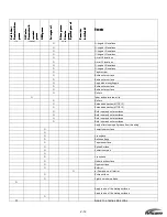
Vapor Separator
•
Wear and damage on seal ring
•
Float
Fuel Feed Pump (FFP)
•
Wear and damage on seals and
grommets
Air rail
•
Wear and damage on O-rings
Air regulator
•
Air pressure
•
550kPa (5.6 kg/cm2) +/- 7% (80 psi +/- 7%)
Fuel regulator
•
Fuel pressure
•
Measured air pr 70 kPa (0.7
kg/cm2) +/- 10% (10 psi +/- 10%)
Air injector
•
Measured value for resistance
•
Operating condition (check for
clicking sound when 12 volts is
applied)
•
1.29 +/- 0.1 ohm (20 deg. C, 68 deg. F)
Fuel injector
•
Measured value for resistance
•
1.8 +/- 0.1 ohm (20 deg. C, 68 deg. F)
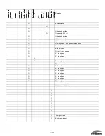
Throttle position sensor
(TPS)
•
Measured values of resistance
between connectors.
•
Between upper and lower connectors: 5.0
ohms +/- 20%
•
Between upper and middle connectors:
resistance value (k ohms)
Fully closed (
Full Open
TPS 1
0.5 to 1
4 to 5
Water Temperature
sensor
•
Measured values of resistance
•
2.6k ohms +/- 10% (20 deg. C; 68 deg. F)
0.3 k ohms +/- 5% (80 deg. C; 176 deg. F)
Oil Level sensor
•
Conductivity
Rectifiers
•
Conductivity
•
Refer to tester checkpoint Table (Chapter 5)
Summary of Contents for 40 hp
Page 3: ......
Page 9: ...1 2 2 O 2 O 2 O 2 Outline Dimensions utline Dimensions utline Dimensions utline Dimensions ...
Page 17: ...1 10 ...
Page 19: ...2 2 ...
Page 20: ...2 1 ...
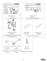
Page 35: ...2 16 5 Special Tools 5 Special Tools 5 Special Tools 5 Special Tools ...
Page 43: ...2 24 ...
Page 48: ...3 5 ...
Page 50: ...3 7 ...
Page 54: ...3 11 ...
Page 57: ...4 2 1 1 1 1 Power Uni Power Uni Power Uni Power Unit t t t ...
Page 60: ...4 5 ...
Page 66: ...4 11 ...
Page 68: ...4 13 ...
Page 72: ...4 17 ...
Page 75: ...4 20 ...
Page 86: ...4 31 ...
Page 97: ...4 42 Piston and Crankshaft Piston and Crankshaft Piston and Crankshaft Piston and Crankshaft ...
Page 106: ...4 51 ...
Page 111: ...5 2 1 1 1 1 Wire Routing Wire Routing Wire Routing Wire Routing ...
Page 112: ...5 3 ...
Page 113: ...5 4 ...
Page 114: ...5 5 ...
Page 115: ...5 6 ...
Page 116: ...5 7 Wiring Diagram 40B 50B EPTO ...
Page 117: ...5 8 ...
Page 118: ...5 9 ...
Page 119: ...5 10 ...
Page 120: ...5 11 ...
Page 121: ...5 12 ...
Page 126: ...5 17 Note Slash shows stripe color of cable 2 2 2 2 Assembly Assembly Assembly Assembly ...
Page 127: ...5 18 Wiring around solenoid Bracket ...
Page 128: ...5 19 ...
Page 129: ...5 20 ...
Page 130: ...5 21 ...
Page 136: ...5 27 Kill Switch Crank Sensor Oil Level Sensor Grounds Air Injector 1 ...
Page 137: ...5 28 Air Injector 2 Air Injector 3 Coil 1 Coil 2 Coil 3 ...
Page 138: ...5 29 Fuel Pump Fuse Box Regulator Stator Complete Wiring harness ...
Page 140: ...6 2 1 1 1 1 Configuration Configuration Configuration Configuration GEARCASE DRIVESHAFT ...
Page 141: ...6 3 GEARCASE PROPELLERSHAFT ...
Page 152: ...6 14 ...
Page 153: ...6 15 ...
Page 185: ...10 20 ...
Page 193: ...11 8 ...