


5-22
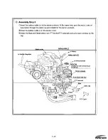
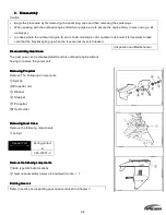
3.
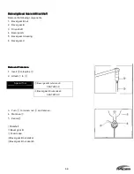
Inspection
Fly wheel Magneto
Precautions
Avoid applying shock or impact to the fly wheel, such as that from the tapping of a hammer.
Be sure to use the recommended tool or equivalent only .Do not use standard pulley puller obtained locally.
Always replace the fly wheel if it has been dropped on the floor or any other hard surface.
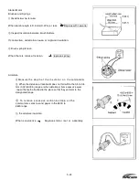
Resistance Values for Coils
These values include ignition coil, alternator coil, air injector, fuel injector and CPS(crank position sensor).
Refer to the section "Specifications and Standards Used in Servicing" in Chapter 2.
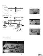
Rectifier Regulator
Inspect
For faulty connections or severed lines in the wire harness.
Measure conductivity and resistance values by referring to the check sheet table below.(Values listed are standard
values.)
Disconnect wiring and measure with regulator isolated from electrical system.
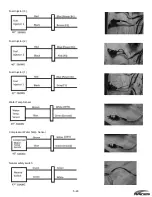
Rectifier Checkpoint Table
lead(red)
Red
Yellow Black
Yellow Yellow
Teste
Lead
Red
OFF
OFF
OFF
OFF
(Blac Yellow ON
(4kΩ)
OFF
OFF
OFF
Black ON(5kΩ) ON
(4kΩ)
ON(4kΩ) ON(4kΩ)
Yellow ON
(4kΩ)
OFF
OFF
OFF
Yellow ON
(4kΩ)
OFF
OFF
OFF
Summary of Contents for 40 hp
Page 3: ......
Page 9: ...1 2 2 O 2 O 2 O 2 Outline Dimensions utline Dimensions utline Dimensions utline Dimensions ...
Page 17: ...1 10 ...
Page 19: ...2 2 ...
Page 20: ...2 1 ...
Page 35: ...2 16 5 Special Tools 5 Special Tools 5 Special Tools 5 Special Tools ...
Page 43: ...2 24 ...
Page 48: ...3 5 ...
Page 50: ...3 7 ...
Page 54: ...3 11 ...
Page 57: ...4 2 1 1 1 1 Power Uni Power Uni Power Uni Power Unit t t t ...
Page 60: ...4 5 ...
Page 66: ...4 11 ...
Page 68: ...4 13 ...
Page 72: ...4 17 ...
Page 75: ...4 20 ...
Page 86: ...4 31 ...
Page 97: ...4 42 Piston and Crankshaft Piston and Crankshaft Piston and Crankshaft Piston and Crankshaft ...
Page 106: ...4 51 ...
Page 111: ...5 2 1 1 1 1 Wire Routing Wire Routing Wire Routing Wire Routing ...
Page 112: ...5 3 ...
Page 113: ...5 4 ...
Page 114: ...5 5 ...
Page 115: ...5 6 ...
Page 116: ...5 7 Wiring Diagram 40B 50B EPTO ...
Page 117: ...5 8 ...
Page 118: ...5 9 ...
Page 119: ...5 10 ...
Page 120: ...5 11 ...
Page 121: ...5 12 ...
Page 126: ...5 17 Note Slash shows stripe color of cable 2 2 2 2 Assembly Assembly Assembly Assembly ...
Page 127: ...5 18 Wiring around solenoid Bracket ...
Page 128: ...5 19 ...
Page 129: ...5 20 ...
Page 130: ...5 21 ...
Page 136: ...5 27 Kill Switch Crank Sensor Oil Level Sensor Grounds Air Injector 1 ...
Page 137: ...5 28 Air Injector 2 Air Injector 3 Coil 1 Coil 2 Coil 3 ...
Page 138: ...5 29 Fuel Pump Fuse Box Regulator Stator Complete Wiring harness ...
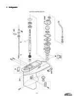
Page 140: ...6 2 1 1 1 1 Configuration Configuration Configuration Configuration GEARCASE DRIVESHAFT ...
Page 141: ...6 3 GEARCASE PROPELLERSHAFT ...
Page 152: ...6 14 ...
Page 153: ...6 15 ...
Page 185: ...10 20 ...
Page 193: ...11 8 ...