


2-23
0000----ring Setting Tool (o24) (3T5
ring Setting Tool (o24) (3T5
ring Setting Tool (o24) (3T5
ring Setting Tool (o24) (3T5----72863
72863
72863
72863----O)
O)
O)
O)
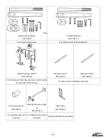
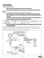
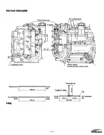
Install the fuel injector 2.8-20.2 0-rings (3T5-1 0304-0).
Apply engine oil to both the 0-rings and the 0-ring setting tool.
Position the 0-ring setting tool in place; then install 0-rings by sliding them on.
..
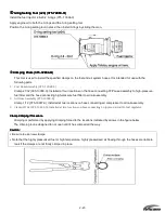
Crimping Pliers (3T5
Crimping Pliers (3T5
Crimping Pliers (3T5
Crimping Pliers (3T5----72864
72864
72864
72864----O)
O)
O)
O)
This tool is used to install the specified clamps on the fuel and air system hoses. It is intended for use with the
following parts.
1.
Fuel Hose Assembly (3T5-1 0089-0)
Clamp 21/32 (385-10086-0): Installed at four locations on the hose connecting FFP case assembly to high-pressure
fuel filter and the hose connecting high-pressure fuel filter to air rail assembly.
2.
Air Hose Assembly (3T5-10088-0)
Clamp 1/12 (3T5-10087-0): Installed at two locations on hose connecting air compressor to air rail assembly.
3.
Clamp 29/64 (3T5-10091-0): Installed at two locations on hose connecting L nipple on air rail to fuel regulator.
Clamp Crimping Procedure
Clamp Crimping Procedure
Clamp Crimping Procedure
Clamp Crimping Procedure
Crimping is performed by applying crimping forced to the locations indicated by arrows in the figure below.
The crimping tool is designed to not open until it has crimped all the way.
Caution:
Caution:
Caution:
Caution:
•
Be sure to use new clamps.
•
Note that the highly pressurized fuel or high temperature, highly pressurized air flowing through the hoses are liable to
leak if the clamps are not firmly crimped in place.
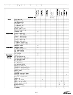
Summary of Contents for 40 hp
Page 3: ......
Page 9: ...1 2 2 O 2 O 2 O 2 Outline Dimensions utline Dimensions utline Dimensions utline Dimensions ...
Page 17: ...1 10 ...
Page 19: ...2 2 ...
Page 20: ...2 1 ...
Page 35: ...2 16 5 Special Tools 5 Special Tools 5 Special Tools 5 Special Tools ...
Page 43: ...2 24 ...
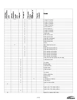
Page 48: ...3 5 ...
Page 50: ...3 7 ...
Page 54: ...3 11 ...
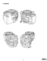
Page 57: ...4 2 1 1 1 1 Power Uni Power Uni Power Uni Power Unit t t t ...
Page 60: ...4 5 ...
Page 66: ...4 11 ...
Page 68: ...4 13 ...
Page 72: ...4 17 ...
Page 75: ...4 20 ...
Page 86: ...4 31 ...
Page 97: ...4 42 Piston and Crankshaft Piston and Crankshaft Piston and Crankshaft Piston and Crankshaft ...
Page 106: ...4 51 ...
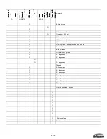
Page 111: ...5 2 1 1 1 1 Wire Routing Wire Routing Wire Routing Wire Routing ...
Page 112: ...5 3 ...
Page 113: ...5 4 ...
Page 114: ...5 5 ...
Page 115: ...5 6 ...
Page 116: ...5 7 Wiring Diagram 40B 50B EPTO ...
Page 117: ...5 8 ...
Page 118: ...5 9 ...
Page 119: ...5 10 ...
Page 120: ...5 11 ...
Page 121: ...5 12 ...
Page 126: ...5 17 Note Slash shows stripe color of cable 2 2 2 2 Assembly Assembly Assembly Assembly ...
Page 127: ...5 18 Wiring around solenoid Bracket ...
Page 128: ...5 19 ...
Page 129: ...5 20 ...
Page 130: ...5 21 ...
Page 136: ...5 27 Kill Switch Crank Sensor Oil Level Sensor Grounds Air Injector 1 ...
Page 137: ...5 28 Air Injector 2 Air Injector 3 Coil 1 Coil 2 Coil 3 ...
Page 138: ...5 29 Fuel Pump Fuse Box Regulator Stator Complete Wiring harness ...
Page 140: ...6 2 1 1 1 1 Configuration Configuration Configuration Configuration GEARCASE DRIVESHAFT ...
Page 141: ...6 3 GEARCASE PROPELLERSHAFT ...
Page 152: ...6 14 ...
Page 153: ...6 15 ...
Page 185: ...10 20 ...
Page 193: ...11 8 ...