Reference
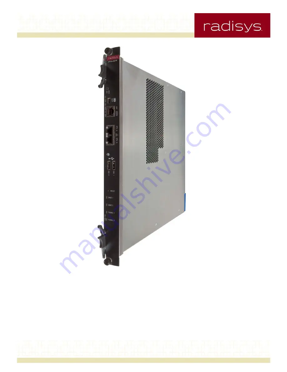
COMPUTE PROCESSING MODULE
ATCA-4616ATCA-4618ATCA-4648
March 2012
007-03446-0000
Page 1: ...Reference COMPUTE PROCESSING MODULE ATCA 4616 ATCA 4618 ATCA 4648 March 2012 007 03446 0000 ...
Page 2: ...ion All rights reserved Radisys is a registered trademark of RadiSys Corporation AdvancedTCA ATCA and PICMG are registered trademarks of PCI Industrial Computer Manufacturers Group All other trademarks registered trademarks service marks and trade names are the property of their respective owners ...
Page 3: ...ternal interfaces 12 Specification compliance 13 Product options 14 Chapter 2 Hardware Description 15 Introduction 15 Functional block diagram 16 ATCA 46xx front panel components 17 Front panel connectors 18 Front panel LEDs 19 Reset and hot swap switches 20 Headers and jumpers 20 Rear panel connectors 21 Alignment keys 21 Zone 1 connector 21 Zone 2 connectors 21 Zone 3 connectors 22 ATCA 46xx boa...
Page 4: ...onal 43 1 8 Solid State Drive SSD module optional 43 eUSB Embedded Flash module optional 44 Chapter 3 Software Firmware Description 45 Introduction 45 System BIOS 45 System BIOS features 45 BIOS setup menus 45 RAS support 58 IPMC functions 61 Software Firmware Update Support 61 Operating System Support 62 Chapter 4 Operation and Maintenance 63 Introduction 63 Hot Swap of the CPM 63 IPMI Over LAN 6...
Page 5: ...stalling an MXM module 75 Removing an MXM module 76 eUSB module installation replacement procedures 76 Installing an eUSB module 77 Removing an eUSB module 77 Troubleshooting Topics 77 General troubleshooting tips 77 Symptoms and recommended actions 78 Sensor alarm troubleshooting 79 Appendix A Specifications 80 Standards and interfaces 80 Environmental specifications 81 Safety specifications 82 M...
Page 6: ...OM serial connector 108 Dual USB connectors 108 Dual Ethernet connectors 109 Mini DisplayPort connector 109 Backplane interfaces 110 Backplane connectivity summary 110 Zone 1 P10 connector pinout 111 Zone 2 J20 connector pinout 112 Zone 2 J23 connector pinout 112 RTM interface pinout 113 Zone 3 J30 connector pinout 113 Zone 3 J31 connector pinout 113 Onboard switches headers and connectors 114 Onb...
Page 7: ...TCA modules Where to get more product information Visit the Radisys web site at www radisys com for product information and other resources Downloads manuals release notes software etc are available at www radisys com downloads See the following resources for information on the CPM not described in this manual Installation and initial setup instructions The ATCA 4xxx Compute Processing Module Inst...
Page 8: ... Web site at www radisys com Standards information For information about the PCI Industrial Computer Manufacturers Group PICMG and the AdvancedTCA standard consult the PICMG Web site http www picmg org Related documents Advanced Switching Core Architecture Specification Revision 1 0 Advanced Switching Interconnect Special Interest Group December 2003 IEC 60950 1 2005 Second Edition International E...
Page 9: ...n Revision 1 0 Intel August 31 2001 PICMG 3 0 Advanced Telecommunications Computing Architecture R3 0 PCI Industrial Computer Manufacturers Group March 24 2008 PICMG 3 1 R1 0 Specification Ethernet Fibre Channel for AdvancedTCA Systems PICMG January 22 2003 PICMG AMC 0 R2 0 Advanced Mezzanine Card Base Specification PCI Industrial Computer Manufacturers Group November 15 2006 PM8380 QuadSMX 3G Qua...
Page 10: ...ap to your wrist and connect its other end to a known ground Handle the carrier only in an area that has its working surfaces floor coverings and chairs connected to a known ground Hold carrier only by its edge and mounting hardware Avoid touching PCB components and connector pins For further information on ESD visit www esda org Notational conventions This manual uses the following conventions Al...
Page 11: ...liance and product options that apply to the ATCA 46xx CPM Major features The following major features apply to the ATCA 46xx CPM Dual Intel Xeon E5 2400 family 64 bit multi core processors using 32 nm process technology Intel C600 series Platform Controller Hub PCH Multiple GbE interfaces Fabric interface supporting 40 GbE connections Intelligent Platform Management Controller IPMC CPU Complex FP...
Page 12: ...ted for the ATCA 46xx CPM Front panel interfaces Dual USB connectors Type A RJ 45 serial port connector RS 232 COM1 Dual RJ 45 GbE connectors Mini DisplayPort connector when optional MXM video module is installed Reset push button Hot Swap extraction switch part of ejector handle LED indicators Blue hot swap LED Red or amber out of service OOS LED Green amber user defined APP LED Green HDD activit...
Page 13: ...ropean requirements for hazardous materials ROHS 6 6 Mechanical and environmental specifications CE FCC Class A VCCI A cUL NEBS Level 3 designed to meet Safety specifications USA UL 60950 1 Canada CSA 22 2 60950 1 EU EN 60950 1 Other IEC 60950 1 Electromagnetic Compatibility EMC specifications Emissions radiated conducted FCC Part 15 and EN 55022 2006 Immunity ESD EN 61000 4 2 radiated EN 61000 4 ...
Page 14: ...eight core processors and no installed memory A4600 MEM xxGB A memory kit consisting of twelve yGB DDR3 VLP registered DIMM RDIMM modules that provides a total of xxGB of RDIMM memory for the CPM A4600 eUSB 32GB A memory expansion option with two eUSB NAND Flash modules with a capacity of 16GB per module A4600 DSSDMXM M A mass storage option with two 1 8 Solid State Disk MLC SSD modules of 64GB ca...
Page 15: ...tal of up to 96 GB per processor or 192 GB total for the module Intel I350 quad Gigabit Ethernet controller that supports two GbE Ethernet ports connected to the Base Interface channels and GbE Ethernet ports routed to the CPM front panel or the RTM interface A Mellanox dual 40 GbE controller that provides two 40 Gb Ethernet ports for the CPM fabric interface Heat sinks to dissipate heat generated...
Page 16: ...PCIe to RTM RTM Link Port 80 Debug Header TPM x16 Gen 3 Dual USB RJ45 DDR3 VLP RDIMMs CH C CH B CH A QPI DDR3 VLP RDIMMs CPU1 CPU0 CH C CH B CH A Optional Dual SSD MXM Module COM2 CPM ATCA 46xx 1000Base T 3G SAS to RTM Dual RJ45 Intel I350 Quad GbE SMGII SerDes to RTM Mellanox CX3 Dual 40G BIOS Flash BIOS Flash MXM 3 0 Type A Module SPI LPC DMI2 USB 2 0 C600 Series Platform Controller Hub PCH SAS ...
Page 17: ...eatures of the CPM Figure 2 shows the CPM front panel and calls out the major features Figure 2 Front Panel Components Thumbscrew Ejector Latch HDD LED OOS LED PWR LED APP LED H S LED Reset Button Ejector Latch Thumbscrew Video MiniDP Connector Serial COM Port Ethernet Ports A B 1000Base T USB Ports 0 1 Base Fabric Channel Status LEDs ...
Page 18: ... option Refer to Table 42 on page 109 for the connector figure and pinout listing of the miniDisplayPort connector During normal operation there is no need to attach a monitor to this connector The two front panel Ethernet connectors provide interfaces to GbE ports with a peak available bandwidth of 100Mbps or 1Gbps Figure 3 shows one of the front panel Ethernet connectors and calls out the Port S...
Page 19: ...ration PWR Health LED Steady Green LED Power ON health good Steady Amber LED Power ON health not good LED off Power OFF APP Customer defined application LED Steady Green LED Controlled by the IPMC with functionality defined by the system implementera Steady Amber LED LED off H S Hot Swap Status LEDb Short Blue blink M5 FRU deactivation request or M6 FRU deactivation in process Steady Blue LED M1 F...
Page 20: ...considered hot swap hardware components Both thumbscrews must be unscrewed in order to remove the CPM from its slot The bottom lock and ejector switch must be disengaged in order to signal to the IPMC that a CPM hot swap is desired The IPMC then controls the hot swap LED and monitors the process Headers and jumpers Refer to Appendix C Onboard switches headers and connectors on page 114 for tables ...
Page 21: ...on connector Refer to Table 44 on page 111 for details Zone 2 connectors The connectors in Zone 2 provide the connections to the Base Interface and Fabric Interface All Fabric connections use point to point 100 Ω differential signals Zone 2 is called Fabric Agnostic which means that any Fabric that can use 100 Ω differential signals can be used with an AdvancedTCA backplane Backplane connector J20...
Page 22: ...ity For details refer to Table 47 on page 113 and Table 48 on page 113 The electrical connections between the CPM and the associated RTM include Switched 3 3V and 12V power under the control of the IPMC One configurable PCI Express port One USB 2 0 Port IPMB L I2 C Bus for an MMC on an RTM IPMC Hot Swap control signals RTM Link interface to CPU Complex FPGA Serial Port 3 3V signals Two 1Gbps SerDe...
Page 23: ... be removed to see and gain access to removable board components jumper blocks or headers Figure 4 shows the CPM board layout and calls out the major components and other features Figure 4 CPM Board Layout CPU1 under heatsink CPU0 under heatsink CPU1 RDIMM bank CPU0 RDIMM bank P10 J20 J23 Mellanox CX3 J30 J31 MXM connector Front panel PCH RTC SuperCAP Customer header eUSB connectors ...
Page 24: ...or each CPU Refer to DIMM memory on page 28 for detailed information The C600 series PCH component Refer to Intel C600 series Platform Controller Hub PCH on page 29 for detailed information Mellanox CX3 dual 10 40 GbE Ethernet controller Refer to Mellanox dual 40GbE controller on page 36 In addition to the components called out in Figure 4 the following components indicated in the Figure 1 block d...
Page 25: ... modulation to reduce processor power and to activate the thermal control circuitry Each CPU includes a single digital thermal sensor DTS that continuously measures the temperature at the processing cores and provides processor die temperature information that represents the worst case temperature for all cores The DTS data represents the difference between the current die temperature and the temp...
Page 26: ...rmal management either by DRAM throttling or by performing a 2X refresh to the memory channels Table 6 Supported Memory Types Mem Rank x Data Width Operating Voltage DIMMs per Channel Memory per DIMM Speed MT s Registered DIMM RDIMM with ECC Single rank x 8 bits 1 5 v One or Two 1 2 4 GB 1066 1333 MHz Single rank x 8 bits LV 1 35 v Two 1 2 4 GB 1066 MHz Dual rank x 8 bits 1 5 v One or Two 2 4 8 GB...
Page 27: ...ows the PCI Express port mapping for each CPU on the CPM Memory The CPM uses memory such as the built in processor cache standard RAM and memory external to any of the existing board components The CPM supports the following types of memory DIMM memory Registered Dual In line Memory Modules RDIMM and Load Reduced Dual In line Memory Modules LRDIMM Non volatile on board memory Flash memory devices ...
Page 28: ...Adding or replacing memory modules on page 73 for the installation procedures Non volatile on board memory The CPM non volatile memory is mainly comprised of the following elements The two 64 Mbit Flash BIOS boot and redundant boot devices The 64 Mbit ME Flash holding the redundant ME firmware IPMI non volatile memory stores IPMC private data and board FRU information The optional eUSB NAND Flash ...
Page 29: ...le of PCI Express Gen2 transfer rates 5 Gb s for a theoretical bandwidth of 20 Gb s in each direction This link is used to pass I O from the SATA SAS LPC and USB peripherals to the CPU or memory along with interrupts and SMI SCI and SERR notification Universal Serial Bus USB The PCH contains two Enhanced Controller Host Interface EHCI controllers providing up to fourteen USB 2 0 ports Each port al...
Page 30: ...ndant ME firmware images On CPM power up the primary BIOS Flash device is selected and used If a corrupt BIOS is detected during operation the IPMC forces a reboot and loads the redundant BIOS Flash image The SPI bus allows the PCH to read and also program the primary and redundant BIOS boot Flash devices as well as the ME firmware Flash device Controlling software as well as on board jumpers prov...
Page 31: ... 8 SMBus and I2 C bus device addresses Device Bus Number Read Address Write Address IPMC FPGA IPMC I2 C bus 2 C1h C0h CPU Complex FPGA IPMC I2 C bus 2 B1h B0h M41T82RM6E RTC IC IPMC I2 C bus 2 D1h D0h PCH SMLink0 IPMC I2 C bus 5 45h 44h PCH SMLink1 IPMC I2 C bus 3 4Dh 4Ch ADM1066 IPMC I2 C bus 3 69h 68h ADM1066 IPMC I2 C bus 3 6Bh 6Ah T0808P IPMC I2 C bus 3 C3h C2h MXM possible address per spec IP...
Page 32: ...cing Monitors with ADC DAC Address 0x6A RTM PCIe ZĞƟmer I C Bus 0 2 I C Bus 1 2 I C Bus 4 2 I C Bus 3 2 I C Bus 2 2 I C Bus 5 2 Address 0x44 RTM PCIe Hotswap Update Channel PCIe Hotswap Address 0x40 Address 0x42 PECI Address 0xD0 Serial RTC Circutry SMLink1 Address 0x4C I350 GbE Controller Addresses LAN0 0x20 LAN2 0x70 LAN1 0x22 LAN3 0x72 Base Front RTM Ethernet Prog Ref POT Address 0x7C Xeon CPU1...
Page 33: ...ces monitor events and log events to a central repository The IPMC is a Radisys designed reusable entity based on the Renesas H8S 2472 microcontroller and Lattice XP2 FPGA The IPMC provides the following features An external 16 bit address data bus with internal 32 bit configuration Internal ROM 512KB of Flash ROM and RAM 40KB 2 MB external SPIBus based Flash ROM Control of front panel LEDs H S OS...
Page 34: ...on page 37 for more information Dual UARTs COM port and SPI mux Two 16550 compatible UARTs are instantiated in the CC FPGA COM1 and COM2 ports can operate up to a 115200 baud rate default of 115 200 baud 8 bit no parity 1 stop bit The CC FPGA is a bridge between the SPI flash programming header the PCH and the redundant 64Mb flash devices The FPGA includes functionality to multiplex the internal U...
Page 35: ...S Sent to I350 port 2 SFP0 TX_FAULT Sent to I350 port 2 SFP0 MOD_DEF0 Sent to I350 port 2 SFP1 RXLOS Sent to I350 port 3 SFP1 TX_FAULT Sent to I350 port 3 SFP1 MOD_DEF0 Sent to I350 port 3 Customer header configuration All control signals configured on the customer and debug headers are routed to the CC FPGA When any signal is in a non default i e LOW state a general flag bit and a state bit are s...
Page 36: ...able of negotiating to x2 and x1 link widths The I350 provides virtualization support including PCI SIG Single Root I O Virtualization VMDq2 support for up to eight virtual machines and eight TX and RX queues per port The I350 has NC SI and SMBus interfaces that support pass through traffic for Serial Over LAN SOL support from the IPMC The CPM has both interfaces connected to allow flexibility for...
Page 37: ...s the RTM PCIe interfaces and the MXM connector In addition to the above reference clocks the following oscillators or crystals are provided on the CPM A 40 000 MHz 100ppm oscillator is provided for the CC FPGA The CC FPGA provides a 6 6 MHz clock for the RTM L interface to the RTM A 32 768 kHz crystal is provided for the PCH RTC A 32 768 kHz crystal is provided for the IPMC RTC A 32 768 kHz cryst...
Page 38: ...lso asserts Powergood Reset normally from the BIOS Memory Retained MR reset A memory retained reset will preserve the contents of main memory while the rest of the system experiences a Platform Reset The intended usage for MR Reset is to provide an operating system kernel crash dump location so that debug information can be recovered after an OS crash When an MR Reset is initiated from one of the ...
Page 39: ...n passed to the system BIOS to disable the timer If the timer is not disabled before it expires the IPMC firmware 1 Disables payload power 2 Selects the secondary boot flash using the Boot Flash Select Control and then 3 Re enables payload power to boot from the secondary SPI flash OS watchdog timer Watchdog 1 This programmable watchdog is used with the BIOS and the Linux OS It can be used by any ...
Page 40: ...s a reset of the IPMC Power subsystems All CPM power is supplied through the P10 backplane connector as 48VDC as specified by the PICMG 3 0 specification The use of DC power minimizes the possibility of RFI and EMI interference for the on board and board to board signals in ATCA components Figure 6 shows the power architecture and distribution for the CPM Input protection and monitoring Each of th...
Page 41: ...mA TPS7A8001 1_5V 1_8V_FR 240mA 150mA USB MXM PCH Misc CX2 PCH I350 TPS54620 1V 3 4A TPS54620 VDD_FE CX2 1 2V CX3 0 9V 2 5A 1_2V_SUS TPS7A8001 TPS54620 1_2V CX2 3 1 83A TPS54620 CPU0 2A NCP6151 90A VCCP0 0 6V 1 35V VCCPLL0 1 8V VSA0 0 85V 20A NCP6151 16A VTT0 1 05V VDDQ0 1 5V 1 35V 50A TPS51100 VTT_DDR0 0 75V 0 675V DDR CPU0 DDR TPS54620 CPU1 2A NCP6151 90A VCCP1 0 6V 1 35V VCCPLL1 1 8V VSA1 0 85V...
Page 42: ...ry the RTM H S LEDs and temperature sensors Payload power supplies The main power supply an isolated quarter brick DC DC convertor the brick is a 48V to 12V convertor It supplies all of the 12VDC power for the CPM With the exception of the 3 3V and 5V output from the PIM all other voltages on the CPM and RTM either come directly from or are converted from the 12V outputs of this brick Refer to Fig...
Page 43: ...ilable with ATCA CPM boards the fan or heat sink for standard MXM video modules cannot be used with the ATCA 46xx CPM Contact Radisys Technical Support for help with a heat sink solution for any selected Type A MXM 3 0 video module The MXM site supports DisplayPort digital video signaling to the front panel and also connects to the x16 PCI Express port from CPU0 port 3 1 8 Solid State Drive SSD mo...
Page 44: ... read speed support of up to 35MB s and write speed up to 17MB s Figure 8 shows an eUSB NAND Flash module ready for installation on the ATCA 46xx CPM Figure 8 eUSB NAND Flash module The modules are stackable with a Bottom version form factor that passes through a USB connection to a Top form factor module providing redundant flash drive support in a small footprint The CPM uses PCH USB ports 2 and...
Page 45: ...ry and option ROM initialization requirements Source code based on UEFI specification Support for the processor and PCH features of the CPM as well as all major board features User configurable through the BIOS Setup utility BIOS setup menus The system BIOS contains a setup utility for modifying the system configuration The system configuration information is maintained in the redundant boot flash...
Page 46: ...page 57 Boot Configuration Boot Option Priorities Security Table 15 Security password Administrator Security password User Save Exit Table 15 Save and Exit options Restore Defaults Save options Boot Override Table 11 Radisys default BIOS Main menu setup options Main menu Submenu Setup Item Values Default BIOS Information BIOS Vendor Dynamic update Core Version Dynamic update Compliancy Dynamic upd...
Page 47: ...s PCI Common Settings VGA Palette Snoop Enabled Disabled PCI Common Settings PERR Generation Enabled Disabled PCI Common Settings SERR Generation Enabled Disabled PCI Subsystem Settings PCI Express Settings PCI Express Device Register Settings Relaxed Ordering Enabled Disabled PCI Express Device Register Settings Extended Tag Enabled Disabled PCI Express Device Register Settings No Snoop Enabled D...
Page 48: ... to 5 0 GT s PCI Express GEN2 Link Register Settings Clock Power Management Enabled Disabled PCI Express GEN2 Link Register Settings Compliance SOS Enabled Disabled PCI Express GEN2 Link Register Settings HW Autonomous Width Enabled Disabled PCI Express GEN2 Link Register Settings HW Autonomous Speed Enabled Disabled PCI Subsystem Settings PCI Hot Plug Settings BIOS Hot Plug Support Enabled Disabl...
Page 49: ...pdate 64 bit Dynamic update Mismatch CPU Dynamic update Hyper threading Enabled Disabled Active Processor Cores All 1 2 3 4 5 6 7 8 9 Limit CPUID Maximum Enabled Disabled Execute Disable Bit Enabled Disabled Hardware Prefetcher Enabled Disabled Adj CacheLine Prefetch Enabled Disabled DCU Streamer Prefetcher Enabled Disabled DCU IP Prefetcher Enabled Disabled Data Reuse Optimization Enabled Disable...
Page 50: ...Duration Watts Short duration power limit 0 Base Frequency Dynamic update MHz 1 2 3 4 5 6 7 8 Core Ratio Limit 0 0 uses the factory configured value for the n Core Ratio Limit value Runtime Error Logging Runtime Error Logging Support Enabled Disabled Mem Err Threshold 10 Max Mem Err Events 10 PCI Error Logging Enabled Disabled Poison Support Enabled Disabled Poison Support in IOH Enabled Disabled ...
Page 51: ...ices USB Devices Dynamic update Based on detected USB devices USB Support Enabled Disabled Legacy USB Support Enabled Disabled Auto EHCI Hand off Enabled Disabled Port 60 64 Emulation Enabled Disabled USB Configuration USB hardware delays and time outs USB transfer time out 1 sec 5 sec 10 sec 20 sec Device reset time out 10 sec 20 sec 30 sec 40 sec Device power up delay Auto Manual Device power up...
Page 52: ...l Type VT100 VT100 a VT UTF8b ANSI Bits per second 9600 19200 38400 57600 115200 Flow Control None Hardware RTS CTS Software Xon Xoff Data Bits 7 8 Parity None Even Odd Mark Space Stop Bits 1 2 Flow Control None Hardware RTS CTS VT UTF8 Combo Key Support Enabled Disabled Recorder Mode Enabled Disabled Resolution 100x31 Enabled Disabled Legacy OS Redirection Resolution 80x24 80x25 Putty KeyPad VT10...
Page 53: ...y 1X Refresh 2X Refresh Mem bandwidth throttling Enabled Disabled Memory ECC Enabled Disabled Memory VDD Energy Saving Max Performance Oppor CKE Power Down Disabled APD ON PPD OFF APD OFF PPD Fast APD OFF PPD Slow APD ON PPD Fast APD ON PPD Slow Self Refresh Enabled Disabled MPST Support Enabled Disabled DDR Speed Limit Auto Force DDR3 800 Force DDR3 1066 Force DDR3 1333 Force DDR3 1600 Force DDR3...
Page 54: ...GEN3 PORT 3A B C D Link Speed GEN1 GEN2 GEN3 CPU 1 PORT 3A B Link Speed GEN1 GEN2 GEN3 MXM PCIe Port x4x4x4x4 x4x4x8 x8x4x4 x8x8 x16 CPU1 IOU2 PCIe Port x4x4x4x4 x4x4x8 x8x4x4 x8x8 x16 RTM PCIe Port x4x4x4x4 x4x4x8 x8x4x4 x8x8 x16 North Bridge IOH Configuration Intel R VT for Directed I O Configuration Intel R VT d Enabled Disabled Coherency Support Enabled Disabled ATS Support Enabled Disabled No...
Page 55: ...bled Disabled PCI Express Ports Configuration DMI Vc1 Control Enabled Disabled DMI Vcp Control Enabled Disabled DMI Vcm Control Enabled Disabled South Bridge ME Subsystem Intel ME Subsystem Configuration ME Subsystem Help Enabled Disabled ME BIOS Interface Version Dynamic update ME Version Dynamic update ME FW Status Value Dynamic update ME FW State Dynamic update ME FW Operation State Dynamic upd...
Page 56: ...EL No Yes On next reset Yes On every reset Erasing Settings When SEL is Full Do Nothing Erase Immediately Custom EFI Logging Options Log EFI Status Codes Disabled Both Error code Progress code IPMI Menu System Information Product Manufacturer Dynamic update Product Name Dynamic update Product Part Number Dynamic update Product Version Dynamic update Product Serial Number Dynamic update Board Manuf...
Page 57: ...teA20 Active Upon Request Always Option ROM Messages Force BIOS Keep Current Interrupt 19 Capture Enabled Disabled Boot Option Priorities Boot Option xxxx Dynamic update Save Exit Page Save Exit options Save Changes and Exit Discard Changes and Exit Save Changes and Reset Discard Changes and Reset Save options Save Changes Discard Changes Restore Defaults Save as User Defaults Restore User Default...
Page 58: ...itches to the standby version and resets the system After boot and during normal operation the IPMC Corrupt Flash Watchdog forces a switch to the secondary boot image by the IPMC if a corrupt boot image is detected that could prevent validation or cause a system hang During normal operation the BIOS program maintains an active write protection on the primary boot image stored in Flash A jumper is ...
Page 59: ...ger critical error action for detected AER errors of the proper severity As with memory errors at runtime PCI errors are signaled to SMI The PCI device causing the error is next determined The SMI routine then clears the error status and reports a platform event to IPMC The SMI handler may then trigger critical error action depending on BIOS setup options Processor and integrated controller error ...
Page 60: ...e BIOS to re attempt booting the boot devices even if it fails The round robin progressive boot causes the BIOS to attempt booting from the next device in the device list until all boot order entries are tried The process repeats indefinitely until a boot attempt succeeds or the system is reset Watchdog support In addition to the RAS features supporting CPM boot the following watchdog timers suppo...
Page 61: ...esets and monitoring managed sensors The CPM s hardware management system complies with the PICMG 3 0 R3 0 base specification the HPM 1 R1 0 firmware upgrade specification and the Intelligent Platform Management Interface IPMI 1 5 specification which defines a set of common interfaces for managing the system and for monitoring system health Using serial over LAN and IPMI over LAN communications th...
Page 62: ...ys Technical Support In all cases a link in the Release Notes points to a separate Firmware and Software Update Instructions manual that provides general update instructions Contact Radisys Technical Support if there are problems or if you have questions about the update process Operating System Support The following Linux operating systems are supported for the CPM Red Hat Enterprise Linux 64 bit...
Page 63: ...nagement application can establish an IPMI over LAN session with the IPMC The IPMC is remotely accessible through the Base Ethernet ports The CPM implements IPMI over LAN using RMCP and RMCP as described in the IPMI 2 0 specification The IPMI over LAN session can be used to enable the functionality described in Serial Over LAN on page 65 Configuring IPMI over LAN access The CPM must be initially c...
Page 64: ...el rsys ipmitool I lan H ShMgr_IP A none t IPMB lan print channel IPMI over LAN additional configuration steps If IPMI over LAN does not work after performing the basic steps 1 Set the user privileges for both channels rsys ipmitool I lan H ShMgr_IP A none t IPMB user priv 1 4 2 rsys ipmitool I lan H ShMgr_IP A none t IPMB user priv 2 4 2 2 Set the channel and administrator access for a channel rs...
Page 65: ...erial Over LAN Serial over LAN SOL is the specification of packet formats and protocols for transmitting serial data over a LAN using IPMI over LAN packets SOL operation is conceptually straightforward A remote management application can establish an IPMI over LAN session with the IPMC Once the session is established the remote console can request SOL session activation In SOL mode any outgoing ch...
Page 66: ...ore you begin on page 63 4 Repeat Step to configure retries for the other Base interface IP address 5 View the retry settings for a Base interface IP address rsys ipmitool I protocol H IP A none C 0 sol info The retry count should be 7 and the retry interval should be 2400 ms 6 Repeat Step 5 to verify access to the remaining interface IP addresses 7 The SOL payload is disabled by default Enter the...
Page 67: ...a SOL session from another window enter rsys ipmitool I protocol H IP A none C 0 sol deactivate Firmware and software upgrade The processes of updating onboard CPM firmware and associated software are covered in separate documents Overall upgrade instructions for onboard firmware and software using rsys_update tools are covered in detail in the ATCA Firmware and Software Update Instructions docume...
Page 68: ...omputer s CPU By specifying the Shelf Manager IP address and the CPM s IPMB address in the update commands By specifying the CPM s Base interface IP address in the update commands This method is available when access to the IPMC has been configured as described in Chapter 4 IPMI Over LAN on page 63 Instructions for upgrading all necessary components are included with the update image which is avai...
Page 69: ...e 75 The eUSB modules For installation or removal procedures see eUSB module installation replacement procedures on page 76 A compatible RTM For installation and removal instructions see the Rear Transition Module Installation Guide Refer to Troubleshooting Topics on page 77 for troubleshooting procedures to use on the CPM Field Replaceable Units FRUs FRU information is stored in non volatile memo...
Page 70: ...connectivity record Carrier clock point to point connectivity record CPM and FRU device IDs The CPM IPMC contains unique identification information Table 17 describes those identifiers Table 17 CPM ID information Field Value Device Name ATCA 46xx Device ID 012h Firmware Version Current Firmware Version in format XX YY IPMI Version 1 5 IPM Support 029h Product ID 01715h Manufacturing ID 0010F1h CPM...
Page 71: ...er force open a locking ejector latch The locking mechanism must be disengaged to release the latch or damage to the latch could occur Do not remove a CPM before its hot swap LED turns solid blue Removing it prematurely can cause unpredictable results in other parts of the system 5 When it is safe to remove the module the hot swap LED stops blinking and remains on WARNING Be careful not to touch a...
Page 72: ...d standoffs 2 Attach the board cover using six flat head Phillips screws Installing the CPM The replacement CPM should already be on a static free surface Perform the following steps to install the replacement RTM or CPM 1 Read Electrostatic discharge on page 10 and make sure you are adequately grounded before handling any of the modules 2 Pick up the CPM 3 Hold the ejector latches in the open pos...
Page 73: ...s chapter see Electrostatic discharge on page 10 Supported DIMM combinations The CPM normally uses registered DIMMs RDIMMs in full sets of twelve identical modules The supported module kits are as follows A4600 MEM 48GB This is a set of twelve modules of 4GB DDR3 VLP RDIMMs A4600 MEM 96GB This is a set of twelve modules of 8GB DDR3 VLP RDIMMs Note The CPM can support memory module sets of DDR3 VLP...
Page 74: ...align the slot keyway of the DIMM with the tab molded in the base of the socket and push the card down firmly into the socket The ejector latches close and click into place when the DIMM is firmly seated 3 Insert the other DIMMs in the same manner 4 Screw the main board cover back into place 5 Power up the CPM and check the BIOS screens to make sure all memory is working After the DIMMs are instal...
Page 75: ...ation will install in the CPM s MXM footprint and connector the constraints imposed by the ATCA board height requires a custom heatsink solution Only Radisys qualified MXM video modules with the Radisys designed heat sink solution can be installed in the CPM Contact Radisys Technical Support if MXM video is necessary Figure 10 shows an MXM module being installed in the CPM Figure 10 MXM module ins...
Page 76: ... 2 Remove the CPM cover see Removing the CPM board cover on page 72 3 Refer to Figure 10 and locate the MXM module near the top front of the CPM 4 Remove the one DSSD module or two MXM video module screws securing the MXM module to the board standoffs 5 Disconnect the MXM module from the MXM connector and set it aside 6 Reinstall the CPM cover see Installing the CPM board cover on page 72 7 Reinst...
Page 77: ...ocate the eUSB module s between the J20 and J23 connectors at the back of the CPM 4 Disconnect the top eUSB module and set it aside If there is a bottom eUSB module disconnect it also and set it aside 5 Reinstall the CPM cover see Installing the CPM board cover on page 72 6 Reinstall the CPM in its slot see Installing the CPM on page 72 Troubleshooting Topics General troubleshooting tips When the ...
Page 78: ...helf s slots installed to properly maintain airflow and emis sions Check temperatures at the air intake on the overheating module and at the platform s air exhaust Use the information to determine whether the overheating might be caused by warm facility air a module failure or a failed fan module If the Radisys Shelf Manager is used see the troubleshooting information in the Shelf Management Softw...
Page 79: ... has booted Verify the serial cable is plugged into both the CPM and the system with the serial connection Verify the CPM is inserted into one of the shelf s node slots Verify the terminal emulation application is set to 115200 bps no parity 8 data bits 1 stop bit with no flow control Verify the default Linux port speed has not been changed in the boot grub grub conf or etc inittab file Message Op...
Page 80: ...ector to the RTM Dual 40GBASE KX4 Fabric Interface Channels controlled by Mellanox CX3 dual 40GbE controller Serial ATA SATA Five Serial ATA II ports from PCH one onboard four to RTM Serial Attached SCSI SAS Three SAS ports from LSISAS1064E to RTM Video interface USB interface Two USB 2 0 ports on front panel two ports available on board four ports to RTM Serial interface One front panel RJ 45 RS ...
Page 81: ...operatinga 5 to 90 RH non condensing at 30 C but not to exceed 0 024 kg water per kg dry air Storage 5 to 90 RH non condensing at 40 C but not to exceed 0 024 kg water per kg dry air Short term storagea 5 to 95 RH non condensing at 40 C but not to exceed 0 024 kg water per kg dry air Altitude Operating Up to 1800 meters 5 905 feet 55 C 1800 meters up to 4000 meters 13 123 feet derated linearly to ...
Page 82: ...eria Product Safety US Accessory Listing UL 60950 1 Safety for Information Technology Equipment Product Safety Canada Approval CSA 22 2 60950 1 03 Safety for Information Technology Equipment Product Safety EU Conformance with the Low Voltage Directive EN 60950 1 Safety for Information Technology Equipment Product Safety Other CB Report IEC 60950 1 Safety for Information Technology Equipment Table ...
Page 83: ...eria A Fast transient burst Operating EN 61000 4 4 0 5 kV 5 50 ns 5 kHz repetition frequency Performance criteria B Surge voltages Operating EN 61000 4 5 Data ports 1 kV 1 2 50 s or 8 20 s DC power port 0 5 kV 1 2 50 s or 8 20 s Performance criteria B Conducted immunity Operating EN 61000 4 6 0 15 80 MHz 3 V 80 AM Performance criteria A Magnetic field immunity Operating EN 61000 4 8 50 Hz 1 A m Pe...
Page 84: ... 3 T3 1 T3 5 Earthquake zone UL60950 1 2nd Edition AS NZS CISPR22 C Tick compliance CNS 13438 compliance Taiwan VCCI Class A compliance Japan GB 9254 compliance China GB 4943 compliance China RRL compliance China RoHS in regards to EFUP markings on the blade and packaging Table 24 Telecommunication specification NEBS requirements Standard Description GR 63 CORE Issue 3 NEBS Requirements Physical P...
Page 85: ... Quality Level II Component failure rates are constant Board to system interconnects are included within estimates Non electrical components screws mechanical latches labels covers etc are not included in estimates General notes Method I Case I Based on parts count Equipment failure is estimated by totaling device failures rates and quantities used Quality Level II Devices purchased to specificati...
Page 86: ...nt panel serial COM port SCI3 provides link to IPMC console while if SCI1 link connected Payload processor link implemented as a KCS port IPMI commands Table 26 presents the commands supported by the CPM in different interfaces These commands are compatible with IPMI v1 5 and PICMG 3 0 R2 0 ECN001 Table 26 Supported IPMI Commands IPMI Command name NetFn Code Command Code Get Device ID App 06h 01h ...
Page 87: ...port App 06h 4Eh Set Event Receiver S E 04h 00h Get Event Receiver S E 04h 01h Platform Event aka Event Message S E 04h 02h Get Device SDR Info S E 04h 20h Get Device SDR S E 04h 21h Reserve Device SDR Repository S E 04h 22h Set Sensor Hysteresis S E 04h 24h Get Sensor Hysteresis S E 04h 25h Set Sensor Threshold S E 04h 26h Get Sensor Threshold S E 04h 27h Set Sensor Event Enable S E 04h 28h Get S...
Page 88: ...G 2Ch 0Ch Get Device Locator Record ID PICMG 2Ch 0Dh Set Port State PICMG 2Ch 0Eh Get Port State PICMG 2Ch 0Fh Compute Power Properties PICMG 2Ch 10h Set Power Level PICMG 2Ch 11h Get Power Level PICMG 2Ch 12h Bused Resource PICMG 2Ch 17h Set AMC Port State PICMG 2Ch 19h Get AMC Port State PICMG 2Ch 1Ah Set Clock State PICMG 2Ch 2Ch Get Clock State PICMG 2Ch 2Dh Get Target Upgrade Capabilities PIC...
Page 89: ...command Restore Factory Defaults OEM Group 2Eh OEM 1 30h 05h Disable CFD OEM Group 2Eh OEM 1 30h E7h Set WDT Reset Type OEM Group 2Eh OEM 1 30h A8h Switch Active Boot Flash OEM Group 2Eh OEM 1 30h A9h Get Active Boot Flash OEM Group 2Eh OEM 1 30h AAh Set Control State for debug only OEM Group 2Eh OEM 1 30h 20h Get Control State for debug only OEM Group 2Eh OEM 1 30h 21h Refer to OEM command descri...
Page 90: ...command allows a BMC Watchdog timeout configured for Hard Reset to cause a Warm Reset or a Cold Reset Table 31 is the command description of the Restore Factory Defaults command Table 29 Get Control State OEM command Data Type Byte Data Field Data Field 1 FRU ID 2 Control number Response Field 1 Completion Code 2 Control State 00h de asserted 01h asserted Table 30 Disable CFD OEM command Data Type...
Page 91: ...gnation is maintained over board power cycles and resets Get Active Boot Flash command This command gets the current Boot Flash and the primary Boot Flash from the H8 IPMI firmware Table 33 is the command description of the Get Active Boot Flash command Table 32 Switch Active Boot Flash OEM command Data Type Byte Data Field Data Field 1 Bit 7 Sets the primary boot flash 0b Do not set 1b Set primar...
Page 92: ...eset Table 34 is the command description of the Get Active Boot Flash command Table 34 RTM Reset Button OEM command Data Type Byte Data Field Data Field 1 Radisys IANA PEN0 F1h 2 Radisys IANA PEN0 10h 3 Radisys IANA PEN0 00h Response Field 1 Completion Code 2 Radisys IANA PEN0 F1h 3 Radisys IANA PEN0 10h 4 Radisys IANA PEN0 00h ...
Page 93: ... to get all hardware shared resources of the onboard x86 processor complex At boot phase 4 the IPMI firmware reconfigures the appropriate control signals to get access to all hardware shared resources and begin the applicable management functions Table 35 is the command description of the Get Active Boot Flash command Table 35 Set Payload Status OEM command Data Type Byte Data Field Data Field 1 R...
Page 94: ...ed the appropriate control signals to regain access of all hardware shared resources and commenced the applicable management functions it shall report the completion of boot phase 4 Table 36 is the command description of the Get Active Boot Flash command Table 36 Get Payload Status OEM command Data Type Byte Data Field Data Field 1 Radisys IANA PEN0 F1h 2 Radisys IANA PEN0 10h 3 Radisys IANA PEN0 ...
Page 95: ...r specific Threshold A threshold sensor has a range of 256 values which represent measurements on the CPM and its FRUs Temperature voltage current and fan speed sensors are examples of threshold sensors Table 37 lists the possible threshold types for the managed sensors Note If the CPM exceeds one of the UNR thresholds the Shelf Manager generates a critical alarm and shuts down the CPM See the Sof...
Page 96: ...ction no interrupt 1Payload Cold Reset 2Payload Power Down 3Payload Power Cycle 4 7Reserved 8Pre Timer interrupt 6 IPMC Watchdog OEM 0xED for IPMC FPGA WDT Digital N A Sensor SDR states that this sensor does not return any analog readings a Get Sensor Reading command directed at this sensor always returns 0 for a reading however an assert event is logged to the SEL once the IPMC is reset due to th...
Page 97: ...ower is good 1 Power fail detected 22 12V RTM PwrFail Power Supply Digital 0 or 1 0 De Asserted 1 Asserted 23 3 3V RTM Fail Power Supply Digital 0 or 1 0 De Asserted 1 Asserted 24 RTM PwrFault Power Supply Digital 0 or 1 0 RTM PwrFault not asserted 1 RTM PwrFault asserted 25 RTM PCIe PwrEn Power Supply Digital 0 or 1 0 RTM PCIe PwrEn not asserted 1 RTM PCIe PwrEn asserted 26 RTM PCIe2 PwrEn Power ...
Page 98: ... UNC 5 25 UC 5 49 UNR 5 74 36 3 3V IPMI Voltage Threshold 3 30 LNR 0 00 LC 2 97 LNC 3 15 UNC 3 47 UC 3 64 UNR 3 8 37 3 3V Voltage Threshold 3 30 LNR 0 00 LC 2 97 LNC 3 15 UNC 3 47 UC 3 64 UNR 3 8 38 1 8V Voltage Threshold 1 80 LNR 0 00 LC 1 62 LNC 1 71 UNC 1 89 UC 1 98 UNR 2 04 39 1 8V FR Voltage Threshold 1 80 LNR 0 00 LC 1 62 LNC 1 71 UNC 1 89 UC 1 98 UNR 2 04 Table 38 ATCA 46xx IPMI Managed Sen...
Page 99: ...UC 1 23 UNR 1 29 43 1V Voltage Threshold 1 00 LNR 0 00 LC 0 90 LNC 0 95 UNC 1 05 UC 1 10 UNR 1 15 44 VCCP0 Voltage Threshold 1 04 VID 0 75 1 35 LNR 0 00 LC 0 72 LNC 0 76 UNC 1 31 UC 1 38 UNR 1 44 45 VCCP1 Voltage Threshold 1 04 VID 0 75 1 35 LNR 0 00 LC 0 72 LNC 0 76 UNC 1 31 UC 1 38 UNR 1 44 46 VDDQ0 Voltage Threshold 1 50 LNR 0 51 LC 1 4 LNC 1 46 UNC 1 56 UC 1 61 UNR 1 66 Table 38 ATCA 46xx IPMI...
Page 100: ...1 00 UNC 1 10 UC 1 12 UNR 1 16 50 VTT DDR0 Voltage Threshold 0 75 LNR 0 50 LC 0 68 LNC 0 71 UNC 0 79 UC 0 83 UNR 0 87 51 VTT DDR1 Voltage Threshold 0 75 LNR 0 50 LC 0 68 LNC 0 71 UNC 0 79 UC 0 83 UNR 0 87 52 2 5V FE Voltage Threshold 2 5 LNR 0 00 LC 2 34 LNC 2 37 UNC 2 63 UC 2 69 UNR 2 76 53 VDD FE Voltage Threshold 1 2 CX2 0 9 CX3 LNR 0 00 LC 1 12 LNC 1 16 UNC 1 25 UC 1 28 UNR 1 32 Table 38 ATCA ...
Page 101: ...60 UNC 1 16 UC 1 20 UNR 1 25 57 VSA1 Voltage Threshold 0 85 LNR 0 00 LC 0 56 LNC 0 60 UNC 1 16 UC 1 20 UNR 1 25 58 1 2V Standby Voltage Threshold 1 20 LNR 0 00 LC 1 08 LNC 1 14 UNC 1 26 UC 1 32 UNR 1 38 59 LVDDQ0 Voltage Threshold 1 35 LV DIMM LNR 0 51 LC 1 26 LNC 1 30 UNC 1 41 UC 1 45 UNR 1 49 60 LVDDQ1 Voltage Threshold 1 35 LV DIMM LNR 0 51 LC 1 26 LNC 1 30 UNC 1 41 UC 1 45 UNR 1 49 Table 38 AT...
Page 102: ...R 10 LC 5 LNC 0 UNC 80 UC 90 UNR 100 64 Inlet Temp 2 Temperature Threshold 25 LNR 10 LC 5 LNC 0 UNC 80 UC 90 UNR 100 65 CPU0 DIMM Temp Temperature Threshold 25 LNR N A LC N A LNC N A UNC 72 UC 80 UNR 95 66 CPU1 DIMM Temp Temperature Threshold 25 LNR N A LC N A LNC N A UNC 72 UC 80 UNR 95 67 PCH Die Temp Temperature Threshold 25 LNR N A LC N A LNC N A UNC 111 UC 116 UNR 121 Table 38 ATCA 46xx IPMI ...
Page 103: ...sets 4h 7h OEM DIMM location 7 6 Reserved 5 3 Channel 00 Channel A on silkscreen 01 Channel B on silkscreen 10 Channel C on silkscreen 11 Unspecified 2 0 DIMM 00 10 According to the label on silkscreen 11 Unspecified Event Data 3 for both event offsets 0h 1h 7 6 Reserved 5 4 Channel number 3 0 DIMM number Event Data 3 for both event offsets 4h 7h OEM data 91 Critical Interrupt Critical Interrupt S...
Page 104: ...the system 02h No usable system memory all installed memory has experienced an unrecoverable failure 03h Unrecoverable hard disk ATAPI IDE device failure 04h Unrecoverable system board failure 05h Unrecoverable diskette subsystem failure 06h Unrecoverable hard disk controller failure 07h Unrecoverable PS 2 or USB keyboard failure 08h Removable boot media not found 09h Unrecoverable video controlle...
Page 105: ...ization 0Bh SM Bus initialization 0Ch Keyboard controller initialization 0Dh Embedded controller management controller initialization 0Eh Docking station attachment 0Fh Enabling docking station 10h Docking station ejection 11h Disabling docking station 12h Calling operating system wake up vector 13h Starting operating system boot process e g calling INT 19h 14h Baseboard or motherboard initializat...
Page 106: ... 0x1 Bank 1 0x2 Bank 2 02h Application Image Corruption IPMI FW Application Image Corruption eventData1 0xA2 Application Image Corrupt eventData2 Currently executing Application Image 0x11 Bank 1 0x22 Bank 2 eventData3 Corrupted Application image 0x11 Bank 1 0x22 Bank 2 95 System Event System Event Sensor specific N A Offset Description 01h OEM System Boot Event 05h Timestamp Clock Synch 96 OEM HP...
Page 107: ...eventData2 1 eventData3 FF Failover Complete 100 HPI Event OEM HPI OEM N A Offset Description 01h OEM HPI Only applicable if Radisys Shelf Manager application is installed eventData1 1 eventData2 3 0 channel 7 4 LUN eventData3 0 120 254 Open for statically added sensors from MXM and dynamically added sensors from RTM Table 38 ATCA 46xx IPMI Managed Sensors continued Sensor Name Type Reading Type N...
Page 108: ... front panel COM serial connector Table 39 COM Serial Connector J6 Dual USB connectors Table 40 lists the pinout for each of the front panel dual USB connectors Note that several unlabeled connection points near pins 1 and 4 on each connector are connection points between the plug and connector shields Table 40 Dual USB Connectors J10 Pin Signal Function 1 RTS Request to Send 2 DTR Data Terminal R...
Page 109: ...net GbE Connectors J8 Mini DisplayPort connector Table 42 lists the pinout for the front panel Mini DisplayPort connector Table 42 Mini DisplayPort connector J5 Pin Signal 1 Channel 0 Data 2 Channel 0 Data 3 Channel 1 Data 4 Channel 2Data 5 Channel 2 Data 6 Channel 1 Data 7 Channel 3Data 8 Channel 3Data 1 8 Pin Signal 1 GND 2 Hot Plug Detect 3 ML_Lane 0 p 4 CONFIG1 5 ML_Lane 0 n 6 CONFIG2 7 GND 8 ...
Page 110: ... or 1000BASE BX KX AMC Port 0 3 1 Option 2 or 9 2 10G BASE BX4 KX4 Port A lane 2 or 1000BASE BX KX AMC Port 8 3 1 Option 9 or Undefined Option 3 10G BASE BX4 KX4 Port A lane 3 3 1 Option 9 or unused Fabric 2 0 10G BASE BX4 KX4 Port B lane 0 or 1000BASE BX KX Port B 3 1 Option 9 Option 1 or Option 2 Dual star Ethernet Fabric interface 1 10G BASE BX4 KX4 Port B lane 1 or 1000BASE BX KX AMC Port 1 3 ...
Page 111: ... 15 SCL_B IPMB Clock Port B Third 16 SDA_B IPMB Data Port B Third 17 18 19 20 21 22 23 24 25 SHELF_GND Shelf Ground Connection to Shelf Ground and safety ground First 26 LOGIC_GND Logic Ground Ground reference and return for front blade to front blade logic signals First 27 ENABLE_B Enable B Short pin for power sequencing Feed B tied to VRTN_B on Backplane Fourth 28 VRTN_A Voltage Return A 48 Volt...
Page 112: ...n individual L shaped ground contact not shown Gray indicates unused pins Table 46 Backplane connector J23 signals Row Interface designation AB CD EF GH 1 Fabric Channel 2 Tx2 2 Tx2 2 Rx2 2 Rx2 2 Tx3 2 Tx3 2 Rx3 2 Rx3 2 2 Tx0 2 Tx0 2 Rx0 2 Rx0 2 Tx1 2 Tx1 2 Rx1 2 Rx1 2 3 Fabric Channel 1 Tx2 1 Tx2 1 Rx2 1 Rx2 1 Tx3 1 Tx3 1 Rx3 1 Rx3 1 4 Tx0 1 Tx0 1 Rx0 1 Rx0 1 Tx1 1 Tx1 1 Rx1 1 Rx1 1 5 Base Channe...
Page 113: ...Gray indicates unused pins Table 48 RTM connector J31 signals Row AB CD EF GH 1 PCIE_RX14 PCIE_RX14 PCIE_TX14 PCIE_TX14 PCIE_RX15 PCIE_RX15 PCIE_TX15 PCIE_TX15 2 PCIE_RX12 PCIE_RX12 PCIE_TX12 PCIE_TX12 PCIE_RX13 PCIE_RX13 PCIE_TX13 PCIE_TX13 3 PCIE_RX10 PCIE_RX10 PCIE_TX10 PCIE_TX10 PCIE_RX11 PCIE_RX11 PCIE_TX11 PCIE_TX11 4 PCIE_RX8 PCIE_RX8 PCIE_TX8 PCIE_TX8 PCIE_RX9 PCIE_RX9 PCIE_TX9 PCIE_TX9 5 ...
Page 114: ...P2 is available during normal operation Refer to Figure 3 on page 18 for the location of the Customer header In order to gain access to the Customer header you will first need to remove the CPM from its slot see Removing the CPM on page 71 and then remove the CPM cover see Removing the CPM board cover on page 72 Table 49 lists the header pin pairs and the actions associated with an installed jumpe...
Page 115: ...uses the ME firmware to stay in the recovery boot loader Onboard connectors The CPM has a number of onboard connectors and other components that are used to expand onboard capabilities The debug connectors along with the onboard power supply LED indicators are normally used only by development manufacturing and troubleshooting personnel The remaining onboard connectors are useful to expand onboard...
Page 116: ...7 GND 158 NC 15 GND 16 NC Reserved 159 NC Reserved 160 NC 17 GND 18 MXM_PWR_LEVEL 161 NC Reserved 162 NC 19 MXM_STD_SW 20 MXM_TH_OVERT 163 NC Reserved 164 NC 21 NC 22 MXM_TH_ALERT 165 NC Reserved 166 GND 23 NC 24 NC 167 NC Reserved 168 NC 25 NC 26 NC 169 NC 170 NC 27 NC 28 NC 171 NC 172 NC 29 HDMI_CEC 30 NC 173 GND 174 GND 31 NC 32 I2C3_PLOAD_SDA 175 NC 176 NC 33 NC 34 I2C3_PLOAD_SCL 177 NC 178 NC...
Page 117: ...245 NC Reserved 246 NC 103 PE3_CPU0_RX_C_DN 6 104 PE3_CPU0_TX_DP 6 247 NC Reserved 248 NC 105 PE3_CPU0_RX_C_DP 6 106 GND 249 NC Reserved 250 GND 107 GND 108 PE3_CPU0_TX_DN 5 251 GND 252 NC 109 PE3_CPU0_RX_C_DN 5 110 PE3_CPU0_TX_DP 5 253 DP_A_L0_N_MXM 254 NC 111 PE3_CPU0_RX_C_DP 5 112 GND 255 DP_A_L0_P_MXM 256 GND 113 GND 114 PE3_CPU0_TX_DN 4 257 GND 258 NC 115 PE3_CPU0_RX_C_DN 4 116 PE3_CPU0_TX_DP...
Page 118: ... Pins Signal P1A 3_3V P1B 3_3V P2A 3_3V P2B 3_3V P3A GND P3B GND P4A GND P4B GND P5A 5V Stuffing option P5B 5V Stuffing option P6A 5V Stuffing option P6B 5V Stuffing option P7A NC P7B NC P8A NC P8B NC P9A NC P9B NC S1A GND S1B GND S2A SATA_RX0 S2B SATA_RX1 S3A SATA_RX0 S3B SATA_RX1 S4A GND S4B GND S5A SATA_TX0 S5B SATA_TX1 S6A SATA_TX0 S6B SATA_TX1 S7A GND S7B GND S8A GND S8B GND S9A NC S9B NC S10...
Page 119: ...o connect an external SATA device to the CPM and control it using the PCH SATA controller The external SATA device will need to receive power externally as well The onboard SATA connector is located near the upper front panel of the CPM between any installed MXM module and the front panel Table 53 lists the pinout for the onboard SATA connector Table 52 eUSB connector pinout Pin Signal Pin Signal ...