Installation Manual
COMBI - TA01A011.B1003
8
ELECTRICAL CONNECTIONS
For qualified personell only:
the boiler works with 230 V 50 Hz AC current and has maximum input
of 170 W. Connection to the electrical mains must be performed with a
device having an omnipolar opening of at least 3 mm. Make sure the
live and neutral connections conform to the diagram.
A secure earth connection is compulsory according to national
and local ragulations.
IMPORTANT
If you need to replace the power supply cable, use cable having the same
characteristics: (HO5 W-F) 3x1 with maximum external diameter 8 mm.).
Connect to the terminal block located in the instrument panel as follows:
A.
Turn off the electrical power supply at the mains.
B.
Remove the boiler front casing.
C.
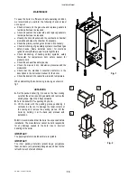
Undo the two screws on the panel and turn it to the position shown in
fig.1 (pos. 1).
D.
After pulling the panel downwards, undo the screws on the housing and
open the small rear panel plate as shown in the figure 1.
E.
With the electrical box now open make the following connections.
•
Connect the yellow/green wire to the terminal marked with the earth
symbol “ “ (see fig.1).
•
Connect the blue wire to the terminal marked with the letter “N”.
•
Connect the brown wire to the terminal marked with the letter “L”.
•
Terminal identified as:
Ta
⇒
Room thermostat
Se
⇒
External sensor
Fig. 2
Fig. 1
M12
M5
M6
M7
M3
M13
M4
orange
M2
M1
orange
orange
beown
yellow/green
L
Se
Ta
NS
e
Ta
pwe
r sup
p
ly
cable
M10
M11
M8
M9
orange
orange
black
black
blue
blue
Summary of Contents for RSF 30
Page 2: ......


