Installation
QUBEVSM-V01-R0 Installation and Operation Manual
Intelligent Electric Vehicle Chargepoints
February 2023
Page
16
of
42
8. Drill the 4x marked fixing holes in the wall and insert the wall plugs.
9. If required, drill the wall for at the cable aperture locations.
10. Secure the mounting bracket to the wall with the 4x screws from the fixing kit.
11. Cut a neat hole in the charger body to allow entry of the power cable and the cable sealing
gland.
x
Ideally, the cable should enter the unit from below or through the back of the
enclosure.
x
A suitable cable gland must be used to maintain the IP of the unit.
x
If a CT and/or ethernet communications will be used, space may be required for
additional holes and cable glands.
12. Make sure any installation debris is removed from the charger enclosure and the internal
components.
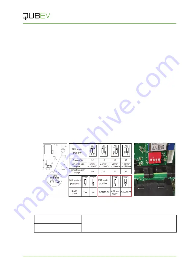
13. If required, adjust the charger output power using the DIP switches.
Factory Default
= 32Amps.
x
The DIP switches are located behind the PEN module which may need to be
temporarily removed for access. To gain access…
x
remove the securing screw from each end of the DIN rail that holds the PEN
module and the incoming power terminals.
x
carefully lift the DIN and the attached components away.
x
Set the DIP switches to the required output as indicated in the illustration below.
Figure 8 DIP Switch Positions
14. Make a record of the Amps setting here.
Amps:
Signature:
Date:
Name:
15. If required, set the Control method DIP switch to
App and OCPP
or to
Only OCPP
, as
shown in the illustration above.
Factory Default
= App and OCPP.


