


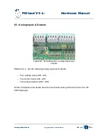


PiXtend V2 -L- Hardware Manual
Connection Notes
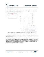
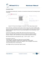
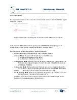
The following diagram illustrates the connection of analog voltage sensors and analog
outputs to the analog inputs of PiXtend V2 -L-.
The voltage inputs can be used for various tasks which require measuring a voltage.
Figure 71 shows a simple circuit with a light-sensitive resistor (LDR) or the evaluation of a
rotary potentiometer.
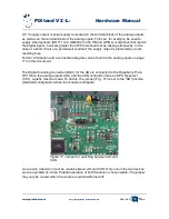
If the 5 V range is used, one of the two +5V power supplies of PiXtend V2 -L- can be used
for the supply of sensors or voltage dividers. Currents greater than 100 mA should not be
taken permanently. In the case of a short circuit or a permanent overload, however, the
supply output is protected by a self-resetting fuse.
www.pixtend.com
Copyright by Qube Solutions GmbH
114 / 146
Figure 71: Principle circuit diagram: Connection of the analog voltage inputs


