background image

Chapter 2: Hardware Overview

StorNext M660 Components

StorNext M660 Metadata Appliance  Hardware Guide

29

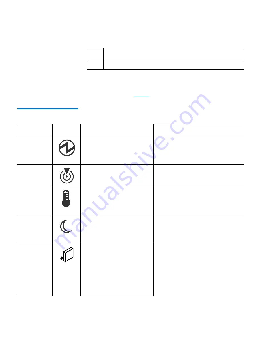
Metadata Array — General LED Behavior

For more information about the Metadata Array LED locations and 

general behavior, see 

Table 6

.

Table 6  Metadata Array – LED 
Locations and Behavior

13

Seven-Segment Displays

Item

Description

LED

Icon

Location

General Behavior

Power


• Drive  enclosure
• Controller
• Power Supply/Cooling Fans

On

 – Power is applied to the drive tray 

or the canister.

Off

 – Power is not applied to the drive 

tray or the canister.

Locate

• Front bezel on the drive tray

On or blinking

 – Indicates the drive 

tray that you are trying to find.

Over-

Temperature

• Front bezel on the drive tray

On

 – The temperature of the drive tray 

has reached an unsafe condition.

Off

 – The temperature of the drive tray 

is within operational range.

Standby 

Power

• Front bezel on the drive tray

On

 – The drive tray is in Standby mode, 

and the main DC power is off.

Off

 – The drive tray is not in Standby 

mode, and the main DC power is on.

Service 

Action 

Allowed

• Controller canister
• Power-fan  canister
• Drive

On

 – It is safe to remove the Controller 

canister, the power-fan canister, or the 

drive.

Off

 – Do not remove the Controller 

canister, the power-fan canister, or the 

drive.

Note:

The drive has an LED, but no 

symbol.

Summary of Contents for StorNext M660

Page 1: ...TIP How to Navigate this PDF Hardware Guide StorNext M660 Metadata Appliance 6 67639 01 Rev G...

Page 2: ...ntum Logo Backup Recovery Archive It s What We Do Be Certain Be Quantum Certain DLT the DLT Logo DLTSage DLTtape the DLTtape Logo DXi DXi Accent Dynamic Powerdown FastSense FlexLink GoProtect GoVault...

Page 3: ...With Adobe Reader 2 About the StorNext M660 Hardware 4 About the StorNext M660 Metadata Appliance 4 Hardware Specification 5 Network Connectivity 5 Base System and Expansion Unit Description 5 StorNe...

Page 4: ...c System Operations 49 Powering On All StorNext M660 System Components 50 Shutting Down All StorNext M660 System Components 53 Powering On a Single MDC Node of the StorNext M660 54 Shutting Down a Sin...

Page 5: ...Contents StorNext M660 Metadata Appliance Hardware Guide v Changing the MDC VIP Address 72 StorNext Operations 74 Chapter 4 Contacting Quantum 77 Comments 77...

Page 6: ...Contents vi StorNext M660 Metadata Appliance Hardware Guide...

Page 7: ...g chapters Chapter 1 Introduction provides an overview of this StorNext M660 Hardware Guide and also includes document conventions product safety statements a list of related documents and supported I...

Page 8: ...Product Safety Statements on page 9 provides multi lingual safety and regulatory statements Navigating This Document With Adobe Reader How to Navigate this PDF Have you ever clicked on a link or a bo...

Page 9: ...oolbar Items Page Navigation and click Previous View 3 Go to View Show Hide Toolbar Items Page Navigation and click Next View The Previous and Next View buttons are now shown Note If your Reader windo...

Page 10: ...o models the StorNext M661 and M662 Note At times this guide uses StorNext M660 as a generic term that applies to the StorNext M661 and the StorNext M662 models When information pertains to a specific...

Page 11: ...le 1GbE Ethernet ports per node The StorNext M662feature two 10 GbE and seven 1 GbE configurable Ethernet ports per node MDCs coordinate SAN file access across SAN clients Additionally the standby nod...

Page 12: ...e gateway functionality for StorNext M662 Metadata Appliances connected to Lattus systems While there are no functional issues in enabling the LAN gateway functionality within a Lattus environment obs...

Page 13: ...used throughout this guide Note Note Emphasizes important information related to the main topic Consequences if not followed There are no hazardous or damaging consequences Caution Caution Indicates...

Page 14: ...you face the component being described Left side of the system Refers to the left side as you face the component being described Conventions Examples For all UNIX based commands the prompt is implied...

Page 15: ...arising from unauthorized use of the product The user assumes all risk in this aspect This unit is engineered and manufactured to meet all safety and regulatory requirements Be aware that improper us...

Page 16: ...tion Product Safety Statements 10 StorNext M660 Metadata Appliance Hardware Guide WARNING Before operating this product read all instructions and warnings in this document and in the system safety and...

Page 17: ...Chapter 1 Introduction Product Safety Statements StorNext M660 Metadata Appliance Hardware Guide 11...

Page 18: ...Chapter 1 Introduction Product Safety Statements 12 StorNext M660 Metadata Appliance Hardware Guide...

Page 19: ...ontains the following sections StorNext M660 Components StorNext M660 Connectivity on page 34 Relocating the StorNext M660 System on page 47 StorNext M660 Components The StorNext M660 Metadata Applian...

Page 20: ...al expansion unit Figure 1 StorNext M660 Base System Components Front StorNext M660 MDC Nodes The two StorNext M660 MDC Nodes are servers that provide storage and control for the StorNext M660 platfor...

Page 21: ...1 StorNext M660 MDC Node Front View Indicators and Buttons StorNext Software Empty Drive Slots Item Indicators and Buttons Description 1 Service tag The slide out tab for the system information includ...

Page 22: ...s and buttons are reserved for Quantum Service For more information see MDC Node Hard Drive Indicator Patterns on page 16 3 LCD panel The LCD panel shows the system ID status information and system er...

Page 23: ...ndicators 1 2 Drive Status Indicator Pattern RAID Only Condition Blinks green two times per second Identify drive preparing for removal Off Drive ready for insertion or removal Note When system power...

Page 24: ...ectors and buttons Unlabeled indicators connectors and buttons are reserved for Quantum Service Figure 4 shows the rear indicators connectors and buttons of the system Figure 4 StorNext M661 MDC Node...

Page 25: ...2 4 port 1 GbE Ethernet HBA 3 PCIe slot 3 4 port 8Gb FC HBA 4 PCIe slot 4 2 port 6Gb SAS HBA 5 iDRACport Reserved for Quantum Service Each node has a unique IP address Node 1 IP address 10 17 21 51 No...

Page 26: ...1 Link indicator 2 Activity indicator 1 2 Indicator Status Indicator Code Link and activity indicators are off The NIC is not connected to the network Link indicator is green The NIC is connected to...

Page 27: ...sent or if a power fault has occurred Figure 7 MDC Node Power Supply Indicator Table 4 Power Supply Status Indicator Indicator Status Indicator Code Not lit AC power is not connected Green In standby...

Page 28: ...bining AC and DC power supplies is not supported and triggers a mismatch StorNext M660 Metadata Array The StorNext M660 features the following Metadata Arrays StorNext M660 Metadata Array on page 22 S...

Page 29: ...660 Metadata Array has a series of indicators and buttons located on the front and back of the array Metadata Array Front View on page 24 Metadata Array Rear View on page 25 Note There are two generat...

Page 30: ...ains the left end cap which contains the drive tray LEDs the right end cap and the drives see Figure 8 Figure 8 StorNext M660 Metadata Array Front View Metadata Array Front LEDs The front of the StorN...

Page 31: ...roller Here are a few simple ways you can identify the Tahoe controller from the Snowmass Controller Item Icon LED Description Color On Off 1 Drive Tray Locate White Identifies a drive tray that you a...

Page 32: ...1 Port 2 ID Diag Lnk Lnk Tahoe Controller Snowmass Controller 1 2 3 4 5 Item Description Found in Controller 1 Serial Port Snowmass only 2 12 Gb SAS Port square Tahoe only 6 Gb SAS Port rectangle Sno...

Page 33: ...ere are numerous connectors displays and LEDs on the back of the Metadata Array controller see Figure 11 and Figure 12 Unlabeled connectors are reserved for Quantum Service Figure 11 Rear Features and...

Page 34: ...1 12 13 Item Description 1 Host Fault LED 2 Host Active LED 3 Host Port SAS Connector 1 12 Gb Tahoe Controller 6 Gb Snowmass Controller 4 Host Port SAS Connector 2 12 Gb Tahoe Controller 6 Gb Snowmass...

Page 35: ...cate Front bezel on the drive tray On or blinking Indicates the drive tray that you are trying to find Over Temperature Front bezel on the drive tray On The temperature of the drive tray has reached a...

Page 36: ...nt Off AC power is not present DC Power Power fan canister On Regulated DC power from the power fan canister is present Off Regulated DC power from the power fan canister is not present Link Service A...

Page 37: ...ludes the StorNext Storage Manager database The Expansion Unit is supplied with dual Snowmass controllers Each controller provides two 6Gb Serial Attached SCSI SAS host ports with 2 GB of system cache...

Page 38: ...ta Array Canister Locations and Rear Features and Indicators on page 38 Metadata Expansion Unit Rear View The Metadata Expansion Unit contains dual environmental service monitor ESM canisters for conn...

Page 39: ...ed connectors are reserved for Quantum Service Table 7 Metadata Expansion Unit Rear Panel Features and Indicators ID Diag Port 1 Item Description 1 Host Link 1 Fault LED 2 Host Link 2 Fault LED 3 SAS...

Page 40: ...Next M660 Power Cabling StorNext M660 SAS Cabling StorNext M660 SAN Cabling StorNext M660 LAN Cabling StorNext M662 Lattus Cabing StorNext M660 Power Cabling Connect the power cables for each componen...

Page 41: ...y as shown in Figure 19 SAS connectivity between the Expansion Unit and the Metadata Array only occurs when installing an Expansion Unit Note Port 1 Port 2 ID Diag Lnk Lnk Port 1 Port 2 ID Diag Lnk Ln...

Page 42: ...ata Array controller currently in use While both generations of the controller use the same SAS connection order from left to right different cables are used for the connections The Tahoe controller i...

Page 43: ...Metadata Appliance Hardware Guide 37 Figure 17 StorNext M660 SAS Cabling Tahoe Controller Figure 18 StorNext M660 SAS Cabling Tahoe Controller Without Expansion Unit Port 1 Port 2 ID Diag O O Port 1 P...

Page 44: ...Metadata Appliance Hardware Guide Figure 19 StorNext M660 SAS Cabling Snowmass Controller with Expansion Unit Port 1 Port 2 ID Diag Lnk Lnk Port 1 Port 2 ID Diag Lnk Lnk ID Diag Port 1 ID Diag Port 1...

Page 45: ...rface configuration is as follows Two interfaces Eth2 and Eth3 are bonded together by default into bond0 for the Metadata network This bond can be broken in the GUI and the Service menu When not bonde...

Page 46: ...nd not used by the system The remaining five ports can be configured through the GUI in various combinations and bonds for gateway port access Ethernet Port Number Logical Ethernet Port Number Physica...

Page 47: ...data Appliance Hardware Guide 41 Figure 21 shows the two 10GbE and seven 1GbE customer facing Ethernet ports on the StorNext M662 Figure 21 StorNext M662 Network Ports Table 9 identifies the logical p...

Page 48: ...libraries StorNext clients should not be zoned to access the tape drives libraries unless they are acting as a Distributed Data Mover host Ethernet Port Number Logical Ethernet Port Number Physical P...

Page 49: ...ports 3 and 4 for tape The actual zoning configuration for these devices is dependent on variables such as the Fibre Channel switch vendor the WWPN of the HBA ports and the external hardware Connect...

Page 50: ...Figure 23 and another configuration with two interconnect switches for redundancy Figure 24 on page 46 Connecting the M662 to the Lattus system involves cabling Eth8 and Eth9 10GbE ports on both MDC N...

Page 51: ...Overview StorNext M660 Connectivity StorNext M660 Metadata Appliance Hardware Guide 45 Figure 23 StorNext M662 Single Lattus Interconnect Switch Cabling Lattus Interconnect Switch Front M662 Node 2 Re...

Page 52: ...0 Connectivity 46 StorNext M660 Metadata Appliance Hardware Guide Figure 24 StorNext M662 Redundant Lattus Interconnect Switches Cabling Lattus Interconnect Switch 2 Front Lattus Interconnect Switch 1...

Page 53: ...ance Hardware Guide 47 Relocating the StorNext M660 System If you ever need to relocate the StorNext M660 system to a different location please contact Quantum Customer Support for additional informat...

Page 54: ...Chapter 2 Hardware Overview Relocating the StorNext M660 System 48 StorNext M660 Metadata Appliance Hardware Guide...

Page 55: ...m Components on page 53 Powering On a Single MDC Node of the StorNext M660 on page 54 Shutting Down a Single MDC Node of the StorNext M660 on page 55 System Serial Numbers and Service Tag on page 56 B...

Page 56: ...plies Note Before powering up the Metadata Array make sure that the Expansion Unit drive LEDs are all green and the seven segment display on both Expansion Unit controllers indicates 0 This indicates...

Page 57: ...gment LCD displays are located on each controller on the back of the array as shown here 3 Turn on the power switch on the front of each of the MDC Nodes Callout number 3 in Figure 25 on page 52 shows...

Page 58: ...stem Components 52 StorNext M660 Metadata Appliance Hardware Guide Figure 25 StorNext M660 Power On Sequence Port 1 Port 2 ID Diag Lnk Lnk Port 1 Port 2 ID Diag Lnk Lnk ID Diag Port 1 ID Diag Port 1 M...

Page 59: ...e currently acting as the secondary node enter User stornext Password enter the customer supplied password the default password is password 5 Enter sudo rootsh 6 Enter the password for the stornext us...

Page 60: ...ower switch on the front of the MDC node you wish to power on see Figure 26 on page 54 Figure 26 Turning On Single MDC Node Power 2 If you are powering on MDC Node 1 and MDC Node 2 is currently operat...

Page 61: ...or the username at the prompt 3 Enter the stornext password The default password is password but may have been changed after initial configuration 4 At the command prompt enter the following to gain r...

Page 62: ...ut down when your monitor goes blank or you lose your connection with the system 12 Remove power cables from the MDC node Note For systems running a release of StorNext prior to StorNext 5 release 5 1...

Page 63: ...n the LCD panel on the front of each MDC node From the Service Menu of each MDC node In the title bar and on the Help About page of the StorNext M660 Metadata Appliance GUI as shown here Figure 27 Loc...

Page 64: ...ce of certain operations such as truncation policies However the creation of this index can take multiple hours for very large databases TSM will be unavailable after upgrading until the indexing has...

Page 65: ...ances Upgrading the firmware also upgrades StorNext if applicable Note Use the StorNext M660 Metadata Appliance GUI to perform all firmware upgrades and HA conversions Upgrade Considerations Before yo...

Page 66: ...grade a Go to the CSWeb site and log in b Navigate to the StorNext Products page for your appliance on the lefthand side of the CSWeb site look for the appropriate link under the StorNext Products sec...

Page 67: ...quirements Note Metadata array operations and the StorNext file system are unavailable while metadata firmware is installed We refer to suspension of metadata operation as a downtime upgrade since no...

Page 68: ...This is a downtime upgrade 4 7 0 1 07 84 46 4 7 0 07 84 46 4 6 1 07 80 55 4 6 07 80 55 4 3 3 07 80 55 4 3 2 07 80 55 4 3 1 07 80 55 4 3 0 07 80 55 4 2 2 0 1 07 75 17 Note Some StorNext releases are n...

Page 69: ...pgrade of the node acting as secondary Both MDC nodes will need to reboot after the metadata array firmware update is applied Note As of StorNext 5 Release 5 1 1 MDC node reboots after metadata array...

Page 70: ...er node The Storage Manager components will need to be restarted after the HA conversion is complete by clicking the Start button in the Storage Manager panel of the Tools System Control page All upgr...

Page 71: ...ing click Validate After a message informs you that the file is valid click the Upload button located to the right of the Browse button Note Files are automatically validated after you click Apply Ste...

Page 72: ...e secondary MDC node which takes the role of the primary MDC node The GUI will run on the primary MDC node until the secondary MDC node completes its upgrade and the system fails over to the secondary...

Page 73: ...og into the StorNext GUI 2 Choose Tools Firmware Upgrade 3 The Firmware Upgrade page appears 4 Select from the list the file you want to delete and then click Delete If you want to delete multiple fil...

Page 74: ...not identical the MySQL database will not start due to file permission errors which in turn prevents storage manager from fully starting up Follow these steps to configure HA 1 From the StorNext GUI...

Page 75: ...the System Name field along with a port number 4 Click Scan Host The system should resolve the secondary MDC node the MDC Address will auto fill with a value 5 Click Convert to convert the secondary M...

Page 76: ...DDM feature do the following If you use the secondary MDC node as a DDM mover make sure the file systems are mounted Initiating a Graceful System Failover During StorNext 5 release 5 0 or later upgra...

Page 77: ...the primary and leave your SSH connection to this node open Time may vary 9 Open an SSH connection to the MDC node now operating as the primary 10 Login to the command line of the primary MDC node Us...

Page 78: ...rating as the secondary by entering the following at the command line 17 Verify the output is 18 Repeat if desired to fail over to the original system operating as the primary 19 Verify that all clien...

Page 79: ...e following command refer to the vip_control man page or the StorNext Man Pages Reference Guide for information on changing the address 5 To update the firewall rules for the MDC node operating as the...

Page 80: ...Capture State Function section of the latest version of the StorNext User s Guide For instructions on how to capture DSET logs refer to the Capture DSET section of the latest version of the StorNext U...

Page 81: ...Chapter 3 Basic System Operations Additional Common Operations StorNext M660 Metadata Appliance Hardware Guide 75...

Page 82: ...Chapter 3 Basic System Operations Additional Common Operations 76 StorNext M660 Metadata Appliance Hardware Guide...

Page 83: ...swers to frequently asked questions FAQs To request a software upgrade visit http www quantum com ServiceandSupport Upgrade Index aspx For further assistance or if training is desired contact the Quan...

Page 84: ...location Benefit today at http www quantum com ServiceandSupport Index aspx eSupport Submit online service requests update contact information add attachments and receive status updates via email Onli...

Page 85: ...Chapter 4 Contacting Quantum StorNext M660 Metadata Appliance Hardware Guide 79 http www quantum com serviceandsupport warrantyinformation index aspx...

Page 86: ...Chapter 4 Contacting Quantum 80 StorNext M660 Metadata Appliance Hardware Guide...

Reviews: