background image


 PX502 Tape Library Quick Start Guide

4

Table 2   Rack Hole Types

Figure

Description

Square rack holes are the most 
common type of rack holes. They 
can accept either cage nuts which 
mount from the back of the rail or 
clip nuts which clip on from the 
side of the rack rail.

Through holes require clip nuts to 
accept mounting hardware.

Threaded holes require neither 
cage or clip nuts to accept 
mounting hardware.

N

OTE

:

The rails within the rack have a hole pattern that 
repeats throughout the rail. 

X

 marks the screw 

positions. Install nut clips (included in the 
accessory kit) on the rails if necessary.

Cage nut

Clip nut

Clip nut

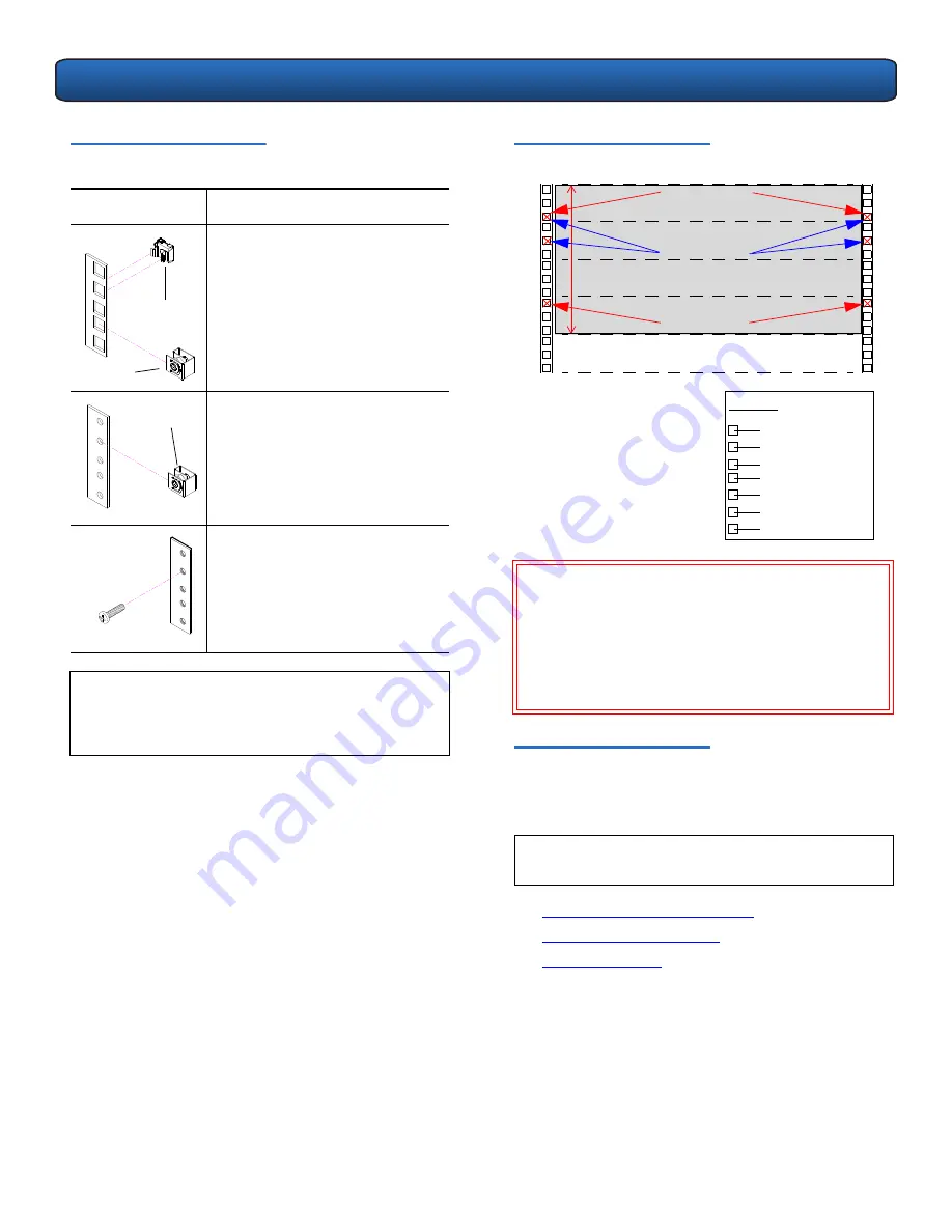
Figure 3  Rail Hole Pattern

Installing the Library

0

Installing the PX502 tape library consists of the following 
steps

:

Installing the Rack Mount Shelves

Installing the Library Chassis

Cabling the Library

W

ARNING

:

If the rack is empty at the time of installation, 

do NOT install the PX502 tape library too 
high in the rack. The weight of the library 
may cause the rack to become “top heavy” 
and unstable if installed in the top of an 
empty rack. Begin installing the PX502 tape 
library from the bottom of the rack if more 
than one library is installed.

N

OTE

:

If this is an upgrade to an existing library system, 
see “Multiple Library Stacks” on page 15.

.625 in (15.9 mm)
.625 in (15.9 mm)
.5 in (12.7 mm)
.625 in (15.9 mm)
.625 in (15.9 mm)

Top of rack

.312 in (7.92 mm)

.5 in (12.7 mm)

Hole pattern

The marks above (

X

indicate the location of 
mounting hardware on the 
rack rails. Ensure that any 
necessary mounting 
hardware is installed on the 
rack rails prior to installing 
the chassis.

1 PX502 Sys

tem

 (4

U

)

1U = 1.75 in

(44.45mm)

4U

Front panel screws 
mounting positions

Back panel screws 
mounting positions

Front panel screws 
mounting positions

Summary of Contents for PX502

Page 1: ...cartridges see figure 1 Notational Conventions 0 This instruction uses the following conventions This document explains how to unpack the PX502 tape library and install it in a standard 19 in rack On...

Page 2: ...ng Necessary Tools 0 Provide the following tools for unpacking and installing the PX502 tape library 1 PHILLIPS screwdriver 2 PHILLIPS screwdriver 1 flat blade screwdriver Allen wrench 2 5mm and 3mm i...

Page 3: ...sory kit Foam PX502 tape library Foam Front bezel Lift point 4 Remove the antistatic sheet a Cut the tape strips securing the sheet b Fold the sheet down c With the help of a second person lift the li...

Page 4: ...Shelves Installing the Library Chassis Cabling the Library WARNING If the rack is empty at the time of installation do NOT install the PX502 tape library too high in the rack The weight of the librar...

Page 5: ...03 screws 2 sets Back bracket hardware M5 x 8 allen screws and mounting plate PN 74 88057 01 bracket PN 90 87275 01 screws 2 sets Back clamp hardware M5 x 10 and back clamp PN 90 87343 08 screws PN 7...

Page 6: ...opening toward back of rack Front of rack Back of rack Back of rack Front of rack Figure 5 Assembling the Left and Right Rack Mount Shelves c Determine the type of rail adapter required for your rack...

Page 7: ...readed circle hole patterns M6 on one side and M5 on the other side Figure 7 Assembling the Left Hand Rack Mount Shelf 2 Install the left and right rack mount shelves into the rack the rack mount shel...

Page 8: ...k Mount Shelves Installing the Library Chassis 0 1 The back mounting brackets are lettered A through I so the correct mounting position is easily determined The mounting positions differ depending on...

Page 9: ...n Use holes G and I X 34 5 to 35 5 in Use holes F and H X 35 5 to 36 5 in Use holes G and I X NOTE If your rack has a depth less than 27 in the back brackets and back clamps are not used 1 Holes 2 Hol...

Page 10: ...unting brackets or clamps Left hand back bracket shown M5 x 10 Allen screws PHILLIPS screws Back mounting clamp Figure 13 Removing the Tape Drive Cover Plates b Insert the tape drive s into the drive...

Page 11: ...drive 1 Tape drive 2 Back of Library SCSI host Ethernet Power Surrogate System Controller Board Tape drive 2 Tape drive 1 Figure 17 PX502 Cable Configuration Native Fibre Channel 2 Connect one end of...

Page 12: ...o gain further access to the internal packaging restraints see figure 19 If there is no space above the PX502 library to remove the top cover continue with Step 3 CAUTION Take standard ESD precautions...

Page 13: ...Avoid touching the printed circuit board CAUTION When removing the foam restraints ensure that the robotics umbilical cable is lying down in the correct position inside the platform and not across th...

Page 14: ...er Table 5 Setting Up the Cabinet Setting the Date and Time 0 To set the date and time 1 From the Setup screen use the up and down arrows to highlight Date and Time and press Enter The Date and Time s...

Page 15: ...re 18 The library shuts down 4 Push the power button to start the library The PX502 tape library is initially configured and ready for use NOTE If you are using DHCP you do not have to setup the follo...

Page 16: ...81 81292 03 B01 81 81292 03 B01 Figure 25 Removing the FlexLink Cover 2 The alignment hardware installed on the top and bottom of the libraries in a multiple stack allow the FlexLink bays to align cor...

Reviews: