40
Fig. 02
QSI0023
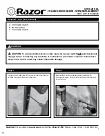
4.14 PARKING LEVER
The parking lever «
1
» is situated at the top of the shield backplate.
With the parking lever «
1
» in position «
3
» the wheels of the vehicle are
free and can turn.
With the parking lever «
1
» in position «
2
» the rear wheel and the HTS
system are locked for parking.
(Fig. 02)
DESCRIPTION OF THE VEHICLE
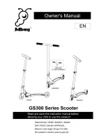
Fig. 01
QSI0022
4.13 - KEY-CONTROLLED SWITCH
The key-controlled switch is situated at the centre of the upper part of
the shield backplate; it is possible to position the switch according to
need in the following positions:
«
OFF
»: engine start up is inhibited.
«
ON
»: the engine can be started.
«
LOCK
»: the steering is locked and the engine cannot be started up.
«
ON/C
»: seat opening.
«
ON/S
»: fuel flap opening
(Fig. 01)
Do not drive with the tilting locking engaged.
A safety device limits the engine speed when the tilting
lock is engaged.
Summary of Contents for 3 2016
Page 1: ...USER MANUAL...
Page 2: ......
Page 7: ...CHAP 1 INTRODUCTION...
Page 10: ...8 INTRODUCTION Page left intentionally blank...
Page 11: ...CHAP 2 SAFETY PRECAUTIONS AND RECOMMENDATIONS...
Page 26: ...Page left intentionally blank...
Page 27: ...CHAP 3 HANDLING AND TRANSPORT...
Page 29: ...CHAP 4 DESCRIPTION OF THE VEHICLE...
Page 32: ...30 DESCRIPTION OF THE VEHICLE QSI0009 4 3 TECHNICAL DATA...
Page 50: ...Page left intentionally blank...
Page 51: ...CHAP 5 VEHICLE USE...
Page 61: ...CHAP 6 VEHICLE MAINTENANCE...
Page 94: ...Page left intentionally blank...
Page 95: ...CHAP 7 PERIODS OF INACTIVITY...
Page 98: ...Page left intentionally blank...
Page 99: ...CHAP 8 DISMANTLING AND DISPOSAL...
Page 101: ...99 NOTES...
Page 102: ...100...
Page 103: ......