


XCubeFAS 3126
Hardware Manual
Deployment Types and Cabling
© 2021 QSAN Technology, Inc. All rights reserved.
www.qsan.com
Official
Document
60
5.2.1.
Single Path Deployment
The following images illustrate some examples of deployment types for single controller
XCubeFAS series.
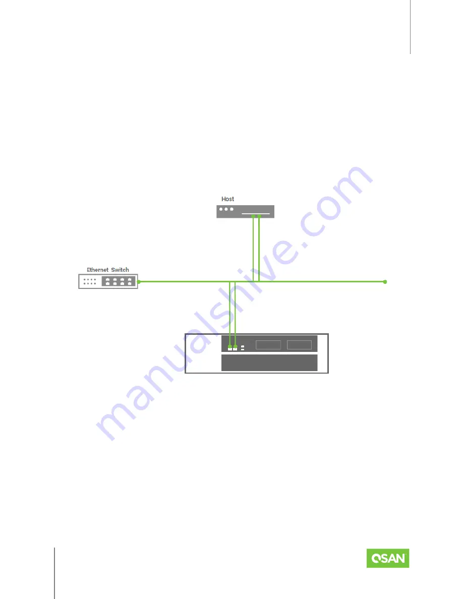
One Host / One XCubeFAS / Single Path
The following figure shows an example of a single controller, direct connect enclosure
configuration with one host accessing the storage. One host is direct connected to the built-in
iSCSI ports in a single controller XCubeFAS series.
Figure 5-1 One Host / One XCubeFAS / Single Path
5.2.2.
Dual Path (MPIO) Deployment
The following images illustrate some examples of deployment types for dual controller
XCubeFAS series. MPIO (Multipath I/O) configurations are designed to provide HA (High
Availability) data connections to ensure data consistency in the rare event of a failure in the
host connectivity from a single path.


