


QSA Global, Inc.
40 North Avenue Burlington, MA 01803
888.272.2242
781.272.2000
qsa-global.com
Operations Manual
MAN-038 March 2019
Page 20 of 100
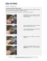
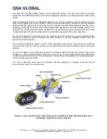
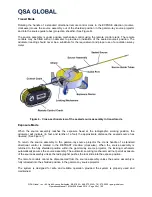
STEP 3 Continued
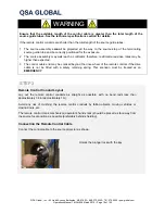
Connecting the Remote Control Cable
ALWAYS use the protective rubber cap whenever the
remote controls are not connected to the gamma-ray
source projector.
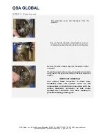
ALWAYS manually move the inner sleeve of the
female connector of the source assembly to the
OPEN position when connecting and disconnecting
the control cable from the source assembly.
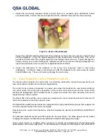
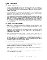
Slide the remote control connector assembly’s collar back
and open the jaws to expose the male portion of the
control cable connector (i.e. the ball-end on the control
cable connector).
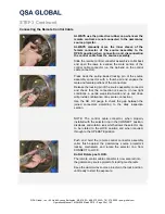
Press back the spring-loaded locking pin of the source
assembly connector with a thumb-nail and engage the
male and female portions of the connectors.
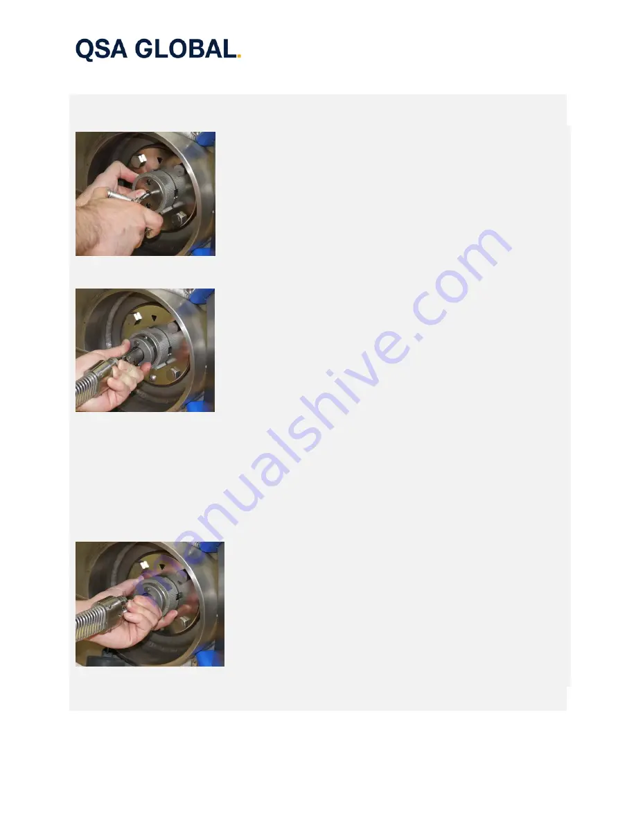
Release the locking pin of the source assembly connector
and check that the connection is secure. (In low light
conditions, a gentle wag side-to-side and up and down
will provide confirmation of a secure connection).
Use the NO GO gauge to check the gap between the
joined connectors according to the daily inspection
section.
NOTE: The control cable connector, when properly
installed with the selector ring in the CONNECT position,
displaces anti-rotation lugs which allows the selector ring
to be rotated to the LOCK position and when required,
through to the OPERATE position.
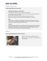
Push and hold the remote control connector assembly
collar flush against the gamma-ray source projector’s
locking mechanism and rotate the selector ring from
CONNECT to LOCK.
Do Not Rotate past LOCK.
The remote control cable connector is now secured into
the gamma-ray source projector’s locking mechanism.
Keep the gamma-ray source projector in the lock position
until ready to start the exposure.
6
7
8


