Making the
Connection
QMS 1725E Print System Getting Started
3-4
a
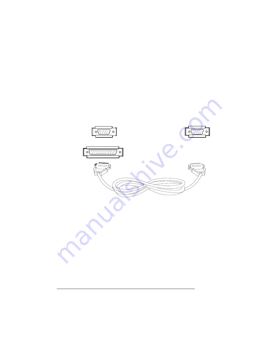
Connect the 25-pin end of the cable to the PC’s parallel port.
b
Tighten all screws.
c
Connect the 36-pin end of the cable to the printer’s parallel
port (it’s labeled “PARALLEL”).
d
Close the clips.
n
Serial Cable
a
Connect the serial cable (with the null modem adapter
attached) to the PC’s 9- or 25-pin male serial port.
b
Connect the other end of the cable to the printer’s serial port
(labeled “SERIAL”).
c
Tighten all screws.
2
Turn on both the printer and the PC.
3
Test communication between the printer and the PC.
You can do this by printing a file from one of your applications, or
you can see the following section, “Testing Communication.”
»
Note: Check your application documentation and Q-FAX (see Appendix
A, QMS Customer Support) for application notes.
To Computer
To Printer
or
9-pin female
25-pin female
9-pin female
Summary of Contents for 1725E
Page 1: ...QMS 1725E Print System Getting Started 1800385 001B...
Page 4: ......
Page 24: ......
Page 40: ......
Page 80: ......
Page 81: ...A QMS Customer Support In This Chapter n Sources of customer support n QMS world wide offices...
Page 87: ...B Configuration Menu In This Chapter n Configuration Menu Diagrams...
Page 89: ...Configuration Menu B 3 Configuration Menu Press...
Page 90: ...Configuration Menu QMS 1725E Print System Getting Started B 4 v Press...


