AP3X Robot User Manual
22 Document Version V1.1.0 (01/11/2023)
2 LAN
5
RTN 2
3 RS-485
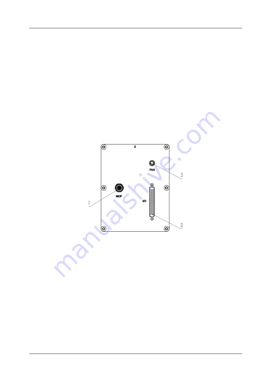
Interface panel 2
The interface panel 1 consists of MCP interface,I/O interface and FAN interface as
shown in Figure 4-2. The system battery is installed behind the panel to save the
system data. The interface panel 2 needs to be removed when the system battery is
replaced.
Figure 4-2 Interface panel 2
1 MCP
3
FAN
2 I/O
Interface panel 3
The interface panel 3 consists of Auxiliary encoder interface,System LED, power
input interface and Brake button as shown in Figure 4-3.


