background image

   qcconveyors.com   

|   Assembly — 

Conveyor Beam Installation


|   7

Drive Unit Installation

Idler End Installation

End Unit Installation

CARET-LEFT

Conveyor Beam Installation

ASSEMBLY

CARET-LEFT

Sticky-note

Note: Assemble the entire conveyor beam structure in the same way. If the conveyor beam is too long to mount onto the support struc-

ture in one continuous length, assemble shorter lengths and connect them to each other once fastened to the suport beams.

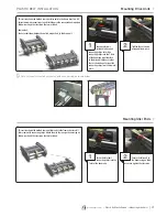
The next step is to connect the straight sections, drive units, idler units and bends to each other. Connect all conveyor beams 
according to instructions below.

Loosen the four set 

screws that are inserted 

into the drive unit connecting 

strips. Insert the connecting strips 

into the T-slot of the beam you 

want attached to the drive unit. 

Make sure the set screws do not 

prevent the connecting strips from 

sliding into place.

1

Make sure that the set

screws do not prevent

the connection strips

from sliding into place.

2

Insert the idler unit 

connecting strips into 

the T- slots of the beam end and 

tighten it.

1

Connect two conveyor

beam ends by inserting

connecting strips into the

beam T-slots. Use two

connecting strips per beam

joint.

1

Tighten the set screws 

using an Allen wrench.

2

Tighten the set screws

using an Allen wrench.

3

Tighten the set screws 

using an Allen wrench.

2

Summary of Contents for FLEXTRAC Series

Page 1: ...ur conveyor s specific information above FLEXTRAC SERIES MANUAL Installation Maintenance MAN FT 2002 4057 Clough Woods Drive Batavia OH 45103 USA 1 513 753 6000 qcconveyors com CONTENTS Introduction p...

Page 2: ...Ensure the necessary tools are available Ensure all the parts and materials included on parts list are available Ensure necessary space for conveyor installation is available Ensure the floor is even...

Page 3: ...Level Power Tools Hand Drill Drill bit TOOLS FASTENERS CARET LEFT To assemble a Flextrac Series conveyor you may need tools listed below Fasteners CARET LEFT Standard Fasteners M8 Washer Counter sunk...

Page 4: ...ve the ability to cut the largest profile in one single cutting action Working site You should use a special area for cutting beams in order to keep the assembly area clean Quality of cut If burrs are...

Page 5: ...your application Insert hex head screws and washers into the holes on the side of the foot Use the screws to fasten foot connecting strips or square nut to the inner side of the foot 1 Thread the hol...

Page 6: ...s of one support bracket into the support beam T slots Tighten the screws Make sure that the support bracket is aligned with the beam 1 Mount the angle bracket to the transverse beam in the same manne...

Page 7: ...eyor beams according to instructions below Loosen the four set screws that are inserted into the drive unit connecting strips Insert the connecting strips into the T slot of the beam you want attached...

Page 8: ...lide rail ends 2 Use the slide rail assembly tool to press the slide rail into place One end of the tool is used when slide rail is mounted onto first side of the beam and the other end is used when m...

Page 9: ...de rail in plain bends or vertical bends since forces are higher on the slide rail in these sections Instead place the joint before the bends Avoid joining slide rail on top of conveyor beam joints St...

Page 10: ...neddrillbit 1 Use a countersink to deburr and countersink the holes Also ensure no metal filings are left underneath the slide rail 2 Insert rivets in the holes using rivet crimping tools to crimp the...

Page 11: ...llbit 1 Use a countersink to deburr and countersink the holes Also make sure no metal filings are left underneath the slide rail 2 Insert screws in the holes using screw bit and hand drill to tighten...

Page 12: ...ough the idler unit and back to the drive unit 2 Insert the chain into the underside of the drive unit Ensure the chain will be moving in the correct direction as indicated by the arrow located at the...

Page 13: ...ce Tube CARET LEFT Insert square nut into T slot of the beam Insert set screw to the square nut 1 Attach the guide rail bracket to the distance tube Tighten the screw Attach the guide rail to the guid...

Page 14: ...ends with set screws and an Allen wrench Make sure you place the connecting sleeves on the outer side of the guide rail 1 To prevent products from being scratched a plastic guide rail cover can be sna...

Page 15: ...ndicated to make sure correct radius of subsequent rails It is possible to bend angles up to 180 minimum radius is 100mm Operate the crank to run the rail back and forth while lowering the upper wheel...

Page 16: ...two connecting strips per beam joint 1 Make sure that the set screws do not prevent the connection from sliding into place 2 Tighten the set screws using Allen wrench 3 Insert end cap on both sides of...

Page 17: ...ert the idler unit connecting strips into the T slot of the beam end 1 Tighten the set screws using an Allen wrench 2 Secure the idler end to the beam using an Allen wrench to tighten the set screws 2...

Page 18: ...d during installation operation and maintenance Some areas present a higher danger to personal safety and because of this various kinds of safety devices must be installed All pinch and shear points a...

Page 19: ...ends in a conveyor will often result in increased wear One reason is that the friction losses are large in plain bends Also the contact surface between chain and slide rail is small and the chain pull...

Page 20: ...will ensure safe maintenance smooth operation and maximum life span of the system Please read and understand this manual before operation or performing maintenance on the system Documentation may not...

Page 21: ...eted 4 Keep area clean Clean up lubricants and other materials before starting conveyor 5 Must equip with Personal Protective Equipment PPE such as safety glasses safety shoes safety helmet etc when p...

Page 22: ...spection Guidelines A suggested maintenance schedule and inspection guidelines are shown below in Maintenance Guidelines It may become evident that the suggested maintenance interval can be extended t...

Page 23: ...actual load against recommended loading Incorrect conveyor chain tension Tension conveyor chain correctly Motor overheating on drive unit Overloaded conveyor Remove products from conveyor and test Ch...

Page 24: ...be given to chain elongation in conveyors of this configuration Gripper conveyors for example are typically configured this way Suspended Drive The suspended drive should be check and lubricated after...

Page 25: ...aution Only warm water 50 C with soap if nec essary may be used for cleaning conveyor chain DEWPOINT Friction Chain Cleated Chain Flocked Chain Finger Gripper Chain Box Gripper Chain and Wedge Chain a...

Page 26: ...be excessive wear on the chain guides and the chain This could be a risk for injury If the slack on the conveyor chain is unacceptably high it must be shortened by splitting the chain and removing the...

Page 27: ...on the slide rail Below shows correct configuration of joints 3 Check that there is a gap between the slide rails and that the joints are correctly fitted 4 Check that the joints are not deformed 5 C...

Page 28: ...nected 2 Disengage the motor there are various methods depending on the type of drive unit 3 Split the chain by removing the steel pin from the pivot Use the special tool for insertion or removal see...

Page 29: ...stance of 10mm between them 2 Joints may not be positioned in bends or in the transition between two sections of beams 3 The slide rails should normally be approximately 5m long on a straight conveyor...

Page 30: ...in completely There are two different methods for fixing slide rail to the conveyor beam Using rivets MA RR 3 this is applicable for MS2 and MM3 series only see previous pages for instructions Using s...

Page 31: ...ail which moves into a wheel bend or a drive unit can block the chain completely There are two different methods for fixing slide rail to the conveyor beam Using rivets MA RR 3 this is applicable for...

Page 32: ...Industrial Series conveyors are available as flat belt plastic chain embedded drive heavy weights and indexing options THE ULTIMATE USER FRIENDLY CONVEYOR Automation Series Single piece aluminum frame...

Reviews: