


Digital Inspection Scope
Page 14 of 19
601575-001-A
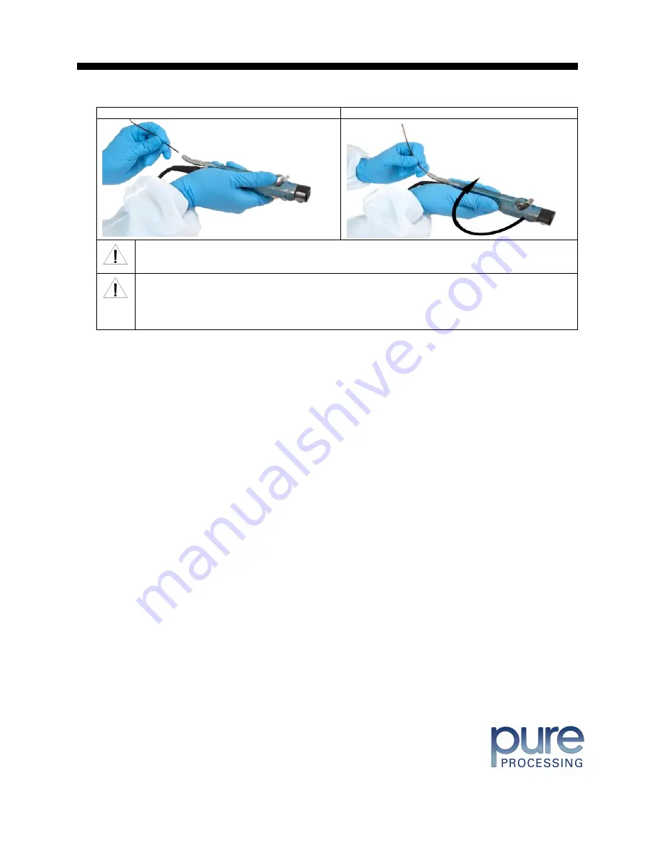
Inserting Borescope in Device
Rotating Device to Avoid Obstacle
WARNING: The minimum bend radius of the Digital Inspection Scope is 0.50
” (12.7 mm). Do
not bend the Inspection Borescope into sharper bend or damage could occur.
WARNING: Do not apply excessive force to the Inspection Borescope. If you feel resistance, or an
obstruction hinders the path of the Inspection Borescope, gently attempt to manipulate or rotate the
device to avoid the obstacle. You may also slowly withdraw a short distance and try advancing
again. Applying excessive force to the Inspection Borescope past an obstacle could result in damage
to the device.
Once the device has reached the end of the area you are inspecting, retract the scope slowly while looking for debris
or damage.
Verifying Operation
Following the steps listed below will ensure the proper use and performance of the Inspection Borescope. The
Inspection Borescope can be checked for normal operation by connecting it as described in the Startup section of
this manual.
Normal operation includes:
•
An image appearing on your computer monitor or HDMI Monitor.
•
A blinking light on Control M
odule near the ‘Power Cycle” button indicates the image feed is transmitting.
•
White light will emit from the distal end of the Inspection Borescope.
•
An LED light on the Control Module front panel will indicate the light intensity setting of the device.


