background image

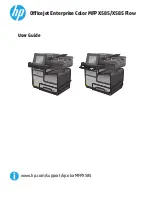
Figure 5. Remote Reset Button Wiring Diagram


SYSTEM DISPLAY

The output display can show one of the following parameters when MODE SELECT is at RUN: kW

or hp, each line current, or each individual line-to-line voltage. The display is also used for

programming the operating parameters of the device. The display also identifies  what caused the

unit to de-energize its relay or what is keeping the unit from energizing its relay. The last fault, not
the current fault, can be displayed by pressing and holding the RESET/PROGRAM button while the

MODE SELECT switch is in the RUN position. When the unit trips off or is holding the motor off, the

current fault condition will be shown in the display without pressing the button. Table 5 below lists

the fault codes the unit could display.

Displayed

Message

Fault

oc

Tripped on overcurrent

SP

Tripped on current single-phasing or unit won’t start because the
voltage is single phased

ub

Tripped on current unbalance

LPR

Tripped on low power

HPR

Tripped on high power

CF

Tripped on contact failure

RP

Incoming phases have been reversed, motor may run backwards if
started

OFF

A stop command was issued from a remote source

Table 5. Fault Codes

COMMUNICATIONS PORT/REMOTE RESET

The unit comes with a 9-pin, sub-D connector for remote communications and/or for using a

remotely located reset button.

If communication is desired, a communication module (part number RS485MS-2W) needs to be


plugged into this 9-pin connector (this is mandatory when communicating with the unit). This module


provides isolation, signal conditioning for compatibility with Modbus RTU and RS-485 networks, and


provides terminals for terminating the shielded communications cable. Up to 99 units can be


installed on one RS-485 network. Further information can be obtained at 

S

ym

C

om

 website

 or


by 

calling at 1-800-8

94

-

0412

.

A remote reset button can be hooked up to the communications module (pn RS485MS-2W) or can

be hooked directly to the 9-pin connector using a male sub-D connector. It should be wired as
shown in Figure 5.

Phone: 800.894.0412 - Fax: 888.723.4773 - Web: www.clrwtr.com - Email: [email protected]

Summary of Contents for 777

Page 1: ... right motor conductor i e the A phase conductor should go through the A round hole See Figure 1 for a typical wiring diagram B For amperage less than 25 amps 1 2 amps for LR model loop the motor conductors according to Table 1 Figure 2 shows an example of the looping required for current ranging from 8 1 to 12 amps MULT 3 C For amperage greater than 90 amps external CTs current transformers are r...

Page 2: ...2 00 10 0 1 1 2 2 5 2 00 10 0 10 10 2 5 3 2 22 11 1 9 9 3 3 5 2 50 12 5 8 8 3 5 4 2 85 14 2 7 7 4 5 3 33 16 6 6 6 5 6 4 00 20 0 5 5 6 8 5 00 25 0 4 4 8 12 6 66 33 3 3 3 12 25 10 0 50 0 2 2 25 90 20 0 100 1 1 uExternal CTs Requiredu 80 110 80 140 5 100 100 5 110 160 120 210 5 150 150 5 160 220 160 280 5 200 200 5 220 320 240 420 5 300 300 5 320 420 320 560 5 400 400 5 400 520 400 700 5 500 500 5 48...

Page 3: ...xample Showing Three Conductors MULT 3 from Table 1 No other necessary connections are shown Figure 3 Typical Wiring Diagram Using External CTs Phone 800 894 0412 Fax 888 723 4773 Web www clrwtr com Email info clrwtr com ...

Page 4: ...ated and set when HP and FLA are programmed so if FLA is not entered EFF must be programmed manually EFF PF EFF PF efficiency power factor can be found on the motor s nameplate or manufacturer s specification sheet If the efficiency rating is available it is best to enter it and FLA should be set to 0 If the efficiency is not available it will automatically be calculated and set according to the H...

Page 5: ...bled OFF RD1 RD1 restart delay one is the rapid cycle timer in seconds This timer is initiated when power is first applied to the unit If no SP or RP conditions exist when power is applied to the device the output relay will energize the NO contact will close and the NC will open once the RD1 timer expires Typically this is set to 20 30 seconds This will provide adequate protection for successive ...

Page 6: ...the 4 20 mA module or to set the Modbus address A01 A99 FS 20 mA 16 mA 4 mA 0 kW 6 FS 8 Example if motor is running at 6 kW Desired mA output 4 20 4 X Running hp kW X FS Output FS full scale setting is required when utilizing a 4 20 mA module PWS should already be set according to the correct hp kW operating range of the motor this will automatically establish the range for FS Set FS according to ...

Page 7: ...PLAY PROGRAM knob until the proper setting for the parameter that is being programmed is displayed 4 Release the RESET PROGRAM button This stores the new parameter in the nonvolatile memory If a setting jumps back to its previous setpoint when changed the tamper guard is locked and must be unlocked before programming can be completed see page 14 for tamper guard procedures 5 Continue steps 1 4 unt...

Page 8: ...ip Most NEMA rated general purpose motors will be protected by this setting 30 Slow Trip Motors with long acceleration times 10 seconds or high inertia loads J prefix Programming any of the trip classes with the J Prefix will enable jam protection This additional protection is enabled 1 minute after the motor starts and provides a 2 second trip time for motors exceeding 400 of the OC setting regar...

Page 9: ...rs E88 OC Service Factor Amperage 8 2 TC General purpose motor 20 CUB Standard NEMA motor 5 PWS 2 1 0 9 95 LPR Normal pumping operation reads 2 86 kW Pump with a momentarily restricted flow dead head reads 1 8 kW Therefore setting is 2 0 kW see PWS for proper range HPR Typically not used set to OFF RD1 To protect the pump from accidental rapid cycling RD 20 seconds RD2 Because the motor may be hot...

Page 10: ...nce LPR Tripped on low power HPR Tripped on high power CF Tripped on contact failure RP Incoming phases have been reversed motor may run backwards if started OFF A stop command was issued from a remote source Table 5 Fault Codes COMMUNICATIONS PORT REMOTE RESET The unit comes with a 9 pin sub D connector for remote communications and or for using a remotely located reset button If communication is...

Page 11: ... down RD2 before restarting Display alternates LPR with run The overload relay has tripped on low power LPR and is timing down RD3 before restarting If LPR is not a normal condition for this installation check for loss of liquid closed valves broken belts etc Display is showing a solid SP ub or oc The unit has tripped on the fault shown and a manual reset is required because the programmed setting...

Page 12: ...Over Setpoint Trip time Over Setpoint Trip time 1 30 seconds 5 6 seconds 2 15 seconds 6 5 seconds 3 10 seconds 10 3 seconds 4 7 5 seconds 15 2 seconds Safety Marks UL UL508 UL1053 CSA LR46510 CE IEC 60947 1 IEC 60947 5 1 Standards Passed Electrostatic Discharge ESD IEC 1000 4 2 Level 3 6kV contact 8kV air Radio Frequency Immunity RFI Conducted IEC 1000 4 6 Level 3 10V m Radio Frequency Immunity RF...

Page 13: ...nd 4 100 650 kW HPR to off to disable these features 5 0 01 1 30 hp 6 1 34 13 3 hp 7 13 4 133 hp 8 134 871 hp LPR Low Power Range determined by PWS HPR High Power Range determined by PWS RD1 Rapid Cycle Timer 0 2 500 Seconds RD2 Restart Delay After All Faults Except Underload motor cool down timer 0 2 500 Minutes RD3 Restart Delay After Underload low flow recovery timer 0 2 500 Seconds A Automatic...

Page 14: ...ppears in the display 4 Release the RESET button 5 Turn MODE SELECT to RUN The program is now locked but all settings can be viewed The unit can be unlocked by following the procedure above except step three adjust DISPLAY PROGRAM until unL appears SymCom warrants its microcontroller based products against defects in material or workmanship for a period of five 5 years from the date of manufacture...

Page 15: ...s above the case ground The 4 20mA module has optical isolation chips to isolate the 4 20mA output from the AC line voltages The signals from the microprocessor go through resistors to provide current limiting before connecting to the 9 pin external connector Therefore the 9 pin SUB D connector on the SymCom unit provides un isolated CMOS signals and is NOT RS232 or TTL compatible Note Do not plug...

Reviews: