background image

I / SAFETY INSTRUCTIONS

Pay special attention to information preceded by the following symbols : 

Indicates a high likelihood of serious or fatal injury if the instruc-
tions are not followed.

CAUTION:

Indicates likelihood of bodily injury or damage to the equipment if the ins-

tructions are not followed. 

NB: 

Provides useful information. 

this symbol reminds you to take care when performing certain operations. 
If you have any problems or questions about the shredder, please contact

an approved dealer. 

WARNING:

the shredder is designed to provide safe and reliable service

under the usage conditions described in the instructions. before using
your shredder, please read and assimilate the content of this manual. Fai-
lure to do so can result in injury or damage to the equipment. 

Training / Information

- Familiarise yourself with correct use of the shredder and its controls before using it.

Make sure you know how to stop the motor quickly. 

- the shredder must always be used in accordance with the recommendations given

in the operating instructions. 

- the user is responsible for accidents or hazards occurring to other people or their 

property. he/she is responsible for assessing any potential risks concerning any 
shredding operation.

- never allow children or people unfamiliar with these instructions to use the shredder.

local regulations may restrict the age of the operator. 

- do not use the shredder after taking medication or substances known to adversely

affect the ability to react or concentrate. 

- When using the shredder, wear appropriate protective equipment, in particular safety

footwear, long trousers, safety glasses, gloves and ear protectors. do not wear loose
clothing or clothing that has hanging cords or ties.

- be aware that there is a slight risk of electric discharge from the spark plug.
- the shredder should be used exclusively for shredding plant matter. using it for any

other purpose could be dangerous or damage the machine. 

Preparation

- carefully inspect the plant matter to be shredded and remove any objects that could

be dangerous (stones, wire, glass, metal objects, etc.). 

- before starting the machine, check that all screws, nuts, bolts and other retaining 

mechanisms  are  properly  secured  and  that  guards  and  screens  are  in  place. 
replace damaged or unreadable warning and operating labels. 

- keep the motor cut-out electric cables in good condition to ensure that cut-out of 

the  motor  is  guaranteed  (at  the  contact  switches  located  near  the  obstruction 
clearance hatch and the feeding chute). 

- check for leaks (petrol, oil, etc.). 
- do not operate the machine within 5 m of bystanders.
- only operate the machine in open space (e.g. not close to a wall or other objects) 

on a firm, level surface. 

- do not operate the shredder on a paved or gravel surface where ejected material 

could cause injury.

Warning! Danger! Petrol is highly flammable 

- store fuel only in containers specifically designed and approved for that purpose. 

Fill with petrol in an outdoor area only and do not smoke during this operation. 

- never remove the petrol tank cap or add petrol when the motor is running or while

it is hot. 

- If you spill petrol on the ground do not start the motor. Move away from the area 

and avoid creating sources of ignition until the petrol vapours have dissipated. 

- store the shredder in a dry place. never store the shredder in a place where petrol

vapours could be ignited by a flame, spark or other strong source of heat. 

- always screw the petrol tank cap on correctly. 
- limit the amount of petrol in the tank to minimise splashes. 
- do not operate the motor in a closed room or area in order to prevent the build-up 

of carbon monoxide vapours. 

- carbon monoxide can be fatal. only operate the shredder in a well-ventilated area.
- the fuel tank should only be drained outdoors.

Operation

- do not work on a slope (the shredder may tip over).
- never pick up or carry the shredder while the motor is running. 

- start the motor carefully in compliance with the manufacturer's instructions and keep

your face and body away from the feeding chute. 

- switch off the motor when the shredder is unattended. 
- do not place hands or any other part of the body or clothing inside the feeding 

chamber, discharge chute, or near any moving part. 

- keep proper balance and footing at all times. do not overreach. never stand at a 

higher level than the base of the machine when feeding material into it.

- always stand clear of the discharge area when operating the shredder. 

When feeding material into the shredder be extremely careful that pieces of metal,
stones, bottles, tins or other foreign objects are not included. 

- In the event of: 

- abnormal noise,
- abnormal vibration, 
- Impact with a foreign object, 
- damage to the motor cut-out cable,

switch off the motor immediately and let the shredder cool down. disconnect the 
spark plug cable, inspect the machine and have any necessary repairs carried out 
by an approved service agent before using again. 

- If the cutting parts get jammed (see § VI-e)
- do not allow processed material to build up in the discharge zone; this may prevent

proper discharge and result in kickback of material through the feed opening. 

- If the shredder is jammed, switch off the power supply and disconnect the spark 

plug cable before removing the debris. keep the power supply free of debris and 
other material to prevent damage to it or potential fire. remember that operating the
starting mechanism on machines with internal combustion engines will also activate
the cutting parts.

- keep all guards and deflectors securely in place and operating correctly.
- Work only in daylight or good artificial light. 
- use of non-approved accessories may make the shredder dangerous and cause 

damage to your machine that will not be covered by your warranty. 

- do not transport the shredder when the power source is on.
- switch off the power source and disconnect the spark plug cable whenever you 

leave the shredder unattended.

- do not tilt the shredder when the motor is switched on..

Maintenance / storage

- switch off the motor and disconnect the spark plug cable before cleaning, checking,

changing tool(s), adjusting or carrying out any maintenance of the shredder.

- switch off the motor, disconnect the spark plug cable and use thick gloves to change

tool(s).

- When servicing the cutting blades, remember that even if the power supply will not

start because of the protective locking mechanism, the cutting blades can still be 
activated by the starter motor.

- keep all nuts and screws fully tightened to guarantee safe operating conditions.
- store the shredder in a place where fuel vapours cannot come into contact with a 

naked flame or sparks. For prolonged storage periods, empty the fuel from the tank
(in an outside area, when using the shredder for the last time before winter, leave 
the motor on until it cuts out through lack of fuel). always let the shredder cool down
before storing.

- to reduce the risk of fire, keep the motor, silencer and petrol storage area free of 

plant matter, excess grease and any other material likely to catch fire.

- Faulty exhaust silencers must be replaced by an approved service agent.
- do not repair worn parts. they must be replaced with original parts by an approved

service agent.

- For your safety, do not modify the specifications of your shredder. do not modify the

motor speed control settings and do not use the motor when running at excessive 
rpm. regular maintenance is essential for safe and efficient performance.

Moving, handling, transport

- this device cannot be used to transport people.
- the motor must be switched off when carrying out any work on the shredder.
- never transport the shredder with the motor on.
- handling: do not lift the shredder alone (see § V-2-g). the weight of the shredder is

shown on the manufacturer's plate and at the end of this manual.

- before transporting the shredder, wait until the cutting assembly has come to a 

complete standstill.

- an appropriate loading ramp must be used to load and unload the shredder into and

from a trailer.

- secure the shredder correctly for safe transport.
- the shredder must be transported in a trailer with the motor off and the spark plug

cable disconnected. do not use any other means of transport.

- this shredder is not suitable for towing without a trailer.

2 - EN

E

N

Summary of Contents for DEVOR X60S-X55L

Page 1: ...5L Notice originale Original instructions Instru es de origem Instrukcja oryginalna www pubert fr CONSIGNES DE SECURITE Pour votre s curit et votre confort d utilisation la lecture compl te de ce manu...

Page 2: ...tatif pour le sujet trait en cas de probl me ou encore pour toute question relative la machine adressez vous un revendeur agr conservez ce manuel port e de main pour le consulter tout moment et assure...

Page 3: ...uverture de la goulotte d alimentation arr ter le moteur quand la machine est sans surveillance ne pas laisser les mains ou toute autre partie du corps ou d un v tement I int rieur de la chambre d ali...

Page 4: ...vous recommandons galement de lire attentivement les consignes de s curit 3 FR Danger lames en rotation garder les mains et les pieds distance des ouvertures lorsque la machine fonctionne 1 Porter une...

Page 5: ...r elle d un moteur install sur une machine d pendra de diff rents facteurs comme la vitesse de rotation les conditions de temp rature d humidit de pression atmosph rique de maintenance et autres Poid...

Page 6: ...goulotte 7 bavette 8 casier de rangement 9 trappe de protection entr e carter de coupe 10 d flecteur 11 bo tier de filtre air 12 bougie d allumage 13 silencieux d chappement 14 bouchon du r servoir d...

Page 7: ...rter de coupe moteur 1 1 2 ensemble goulotte poign e de transport 1 1 3 tube pied broyeur 2 2 4 Pied droit 1 1 5 Pied gauche 1 1 6a roue pleine 2 0 6b roue gonflable 0 2 7 axe de roue 1 1 8 casier 1 1...

Page 8: ...mini 60 mm pos es sur un tabli ou une table Prenez soin de ne pas tre en appui sur des pi ces pouvant tre endommag es capot protection palier vis de fixation contacteur c assembler le pied droit et u...

Page 9: ...pied droit Rep D signation Qt 3 tube pied broyeur 1 5 Pied gauche 1 7 axe de roue 1 14 Vis hM 8 x 16 z emb cr 2 15 Vis hM 8 x 40 z emb cr 4 16 ecrou h M8 z emb cr 6 16 7 16 15 14 15 5 3 16 e assemble...

Page 10: ...b roue gonflable 0 2 9 entretoise roue 2 0 10 rondelle plate 12 4 2 11 rondelle starlock 12 2 2 6a 6b 10 11 9 10 10 9 6a 6b 10 11 g reposer le broyeur sur le sol attention 2 personnes h retirer la tra...

Page 11: ...ar dessus ces crous puis laisser la descendre en appui sur les vis et resserrer les crous 3 Plein en essence 4 Plein en huile SUBARU EP 17 3 4 L SUBARU EP 17 0 6 L LONCIN LC 170 0 6 L LONCIN LC 170 2...

Page 12: ...oite de celle ci pour viter un ventuel retour de ceux ci Veillez ce que personne ne se trouve dans la zone d jection ATTENTION ne travaillez ja mais sans le d flecteur du conduit d jection risque de p...

Page 13: ...pouvoir la tirer puis la faire pivoter compl te ment vers le bas d gager tous les v g taux qui encombrent le broyeur contr ler qu il ne reste rien dans la goulotte d entr e et dans la goulotte d jecti...

Page 14: ...ulotte voir VII a l aide d une cl 6 pans de 5 et d une cl plate de 13 d visser les 4 vis 1 et crou 2 maintenant les 2 couteaux 3 remplacer toujours les 2 couteaux en m me temps Toujours remplacer les...

Page 15: ...t le moteur ce qui deviendrait extr mement dangereux V rifier le niveau d huile moteur et refaire le niveau vidange toutes les 50 heures environ se reporter notice moteur V rifier le niveau d essence...

Page 16: ...e model for the subject being discussed In the event of any problems or for any questions related to the machine please contact an approved reseller Keep this manual close at hand for ease of consulta...

Page 17: ...om the feeding chute switch off the motor when the shredder is unattended do not place hands or any other part of the body or clothing inside the feeding chamber discharge chute or near any moving par...

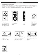
Page 18: ...also recommend that you read the safety instructions carefully 3 EN Danger rotating blades keep hands and feet a safe distance from ope nings when the machine is operating 1 Wear ear protectors and sa...

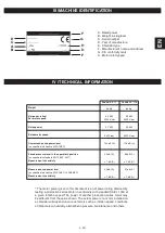
Page 19: ...wer of a motor installed on a shredder will depend on various factors such as rotation speed conditions of temperature humidity atmospheric pressure maintenance and others Weight 64 Kg 64 Kg Net power...

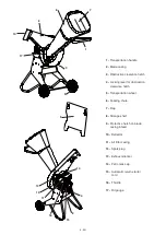
Page 20: ...clearance hatch 5 transportation wheel 6 Feeding chute 7 Flap 8 storage shelf 9 Protective hatch on blade casing infeed 10 deflector 11 air filter casing 12 spark plug 13 exhaust silencer 14 Petro tan...

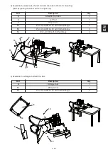
Page 21: ...e transportation handle assembly 1 1 3 shredder foot tube 2 2 4 right foot 1 1 5 left foot 1 1 6a solid wheel 2 0 6b Inflatable wheel 0 2 7 Wheel axle 1 1 8 storage shelf 1 1 9 Wheel spacer 2 0 10 Fla...

Page 22: ...k bench or table ensure that the assembly is not resting on parts that could be damaged bearing protective housing retaining screw contact switch etc c assemble the right foot and one tube to the moto...

Page 23: ...r foot tube 1 5 left foot 1 7 Wheel axle 1 14 Zinc screw hM 8 x 16 with toothed flange 2 15 Zinc screw hM 8 x 40 with toothed flange 4 16 Zinc nut h M8 with toothed flange 6 16 7 16 15 14 15 5 3 16 e...

Page 24: ...g requires 2 people h remove the protective hatch from the blade casing infeed 1 2 3 Ref Description Qty 6a solid wheel 2 0 6b Inflatable wheel 0 2 9 Wheel spacer 2 0 10 Flat washer 12 4 2 11 starlock...

Page 25: ...he flange of the feeding chute over the nuts lower it to slot onto the screws and then tighten the nuts 3 Fill with petrol 4 Fill with oil Warning a no oil label means that you must fill the oil tank...

Page 26: ...lastic feeding chute standing to the right of it to avoid any possible kickback of material Make sure no one is standing in the discharge zone WARNING never operate the shredder without the dis charge...

Page 27: ...then fully pivot downwards clear all the plant matter jam ming the shredder check there is no plant matter in the feeding chute and discharge chute close the hatch follow instruc tions in reverse Mak...

Page 28: ...tch see VI e remove the feeding chute see VII using a 5 mm allen key and a 13 mm open ended spanner unscrew the 4 screws 1 and nuts 2 holding the 2 blades in place 3 always replace the 2 blades at the...

Page 29: ...te is not in place would not automatically cut out the motor which would be extremely dangerous check the motor oil level and carry out an oil change approximately every 50 hours see motor instruction...

Page 30: ...I 2 Fr II 3 Fr III 4 Fr IV 4 Fr V 6 Fr VI 11 Fr VII 12 Fr VIII 13 Fr IX 13 Fr X 13 Fr XI 14 Fr XII 14 Fr 1 RU...

Page 31: ...I 2 RU 5 VI e V 2 g RU...

Page 32: ...II 3 RU 1 2 1 2 3 1 2 2 1 1 2 3 2 1...

Page 33: ...G D H F F A B A B C D E F G ce H IV sae j 1349 64 64 4 2 4 5 4000 4000 3 7 3 5 3400 3200 100 A 100 A 2000 14 CE 90 A 86 A EN 13683 2007 1 A 1 A 95 A 99 A 2000 14 CE 2005 88 EC 1 A 1 A Subaru EP 17 Lon...

Page 34: ...5 RU 1 2 3 4 5 6 7 8 9 10 11 12 13 14 15 16 17 1 3 2 4 8 15 16 11 12 13 14 9 5 17 10 6 7...

Page 35: ...1 1 1 1 2 1 1 3 2 2 4 1 1 5 1 1 6a 2 0 6b 0 2 7 1 1 8 1 1 9 2 0 10 12 4 2 11 starlock 12 2 2 12 rapid M6 4 4 13 6 x16 4 4 14 8 x 16 4 4 15 8 x 40 8 8 16 8 12 12 1 2 3 4 5 6a 6b 8 9 10 11 12 13 14 15 1...

Page 36: ...7 RU 2 a 2 b 2 60 c 3 1 4 1 14 8 x16 2 15 8 x 40 4 16 8 6 16 16 15 14 4 3 15 16...

Page 37: ...8 RU d 3 1 5 1 7 1 14 M 8 x 16 2 15 M 8 x 40 4 16 M 8 6 16 7 16 15 14 15 5 3 16 e 8 1 12 rapid M6 4 13 6 x 16 4 8 12 8 13 13 RU...

Page 38: ...f 6a 2 0 6b 0 2 9 2 0 10 12 4 2 11 starlock 12 2 2 9 RU 6 10 11 9 10 10 9 6 10 11 g h 1 2 3...

Page 39: ...10 RU i i 4 8 3 4 SUBARU EP 17 3 4 SUBARU EP 17 0 6 LONCIN LC 170 0 6 LONCIN LC 170 2 10W30 RU...

Page 40: ...VI a 4 b c 11 RU SUBARU EP 17 LONCIN LC 170 1 2 3 4 5 45 2 1 2 3 4 5 6...

Page 41: ...12 RU d SUBARU EP 17 1 2 LONCIN LC 170 e 4 8 2 VII 1 3 2 RU...

Page 42: ...13 RU 1 VIII 2 IX VI e VII 5 13 4 1 2 2 3 2 24 2 2 4 3 1...

Page 43: ...14 RU X a b XI a 50 b 20 24 c 50 3 24 XII RU...

Page 44: ...is representativo desta categoria se tiver problemas ou d vidas quanto ao equipamento contacte um fornecedor autorizado guarde este manual para refer ncia futura e no caso de venda este deve acompanha...

Page 45: ...ando a m quina est sem vigil ncia n o deixar as m os ou qualquer outra parte do corpo ou roupa no interior da c mara de alimenta o da boca de ejec o ou na proximidade de uma parte m vel Manter em perm...

Page 46: ...ubstitui o recomendado ler com aten o as normas de seguran a 3 PT Perigo l minas em rota o Manter as m os e os p s longe das aberturas quando a m quina est em funcionamento 1 usar uma protec o auditiv...

Page 47: ...de um motor instalado numa m quina depender dos diferentes factores como a velocidade de rota o as condi es de tempe ratura de humidade de press o atmosf rica de manuten o e outros Peso 64 Kg 64 Kg P...

Page 48: ...de entrada 7 resguardo 8 compartimento de arruma o 9 tampa de protec o entrada c rter de corte 10 deflector 11 caixa de filtro de ar 12 Vela de igni o 13 silencioso de escape 14 tampa do dep sito de...

Page 49: ...rte motor 1 1 2 conjunto boca de entrada punho de transporte 1 1 3 tubo p trituradora 2 2 4 P direito 1 1 5 P esquerdo 1 1 6a roda maci a 2 0 6b roda de enchimento 0 2 7 eixo da roda 1 1 8 compartimen...

Page 50: ...mini 60 mm sobre uma bancada ou uma mesa ter cuidado em n o estar apoiado contra pe as que podem ficar danificadas capot protec o chumaceira parafuso de fixa o contactor c Fixar o p direito e um tubo...

Page 51: ...esigna o Qtd 3 tubo p trituradora 1 5 P esquerdo 1 7 eixo da roda 1 14 Parafuso hM 8 x 16 z emb cr 2 15 Parafuso hM 8 x 40 z emb cr 4 16 Porca h M8 z emb cr 6 16 7 16 15 14 15 5 3 16 e Fixar o compart...

Page 52: ...o 2 pessoas h remover a tampa de protec o entrada c rter de corte 1 2 3 Rep Designa o Qtd 6a roda maci a 2 0 6b roda de enchimento 0 2 9 tirante da roda 2 0 10 anilha plana 12 4 2 11 anilha starlock...

Page 53: ...ura por cima destas porcas e deixar descer apoiado sobre os parafusos e apertar as porcas 3 Abastecimento de gasolina 4 Abastecimento de leo Aten o uma etiqueta sem leo indica que deve encher o dep si...

Page 54: ...stico man tendo se direita da mesma para prevenir um eventual re torno dos mesmos ningu m deve estar na zona de ejec o ATEN O nunca trabalhar sem o deflector da conduta de ejec o risco de projec o e p...

Page 55: ...r pux la e faz la rodar completa mente em direc o ao bra o remover todos os vegetais que encravam a trituradora Verifi car se n o h nenhum ele mento remanescente na boca de entrada e na boca de ejec o...

Page 56: ...over a boca de abertura ver VII com uma chave de 6 pontas de 5 e de uma chave plana de 13 desaparafusar os 4 parafusos 1 e porca 2 mantendo as 2 facas 3 substituir sempre as 2 facas ao mesmo tempo Sub...

Page 57: ...ticamente o motor o que seria extremamente perigoso Verificar o n vel de leo do motor e efectuar a substitui o do leo todas as 50 horas aproximadamente ver o manual do motor Verificar o n vel de gasol...

Page 58: ...cz cych urz dzenia nale y skontaktowa si z najbli szym autoryzowanym sprzedawc urz dzenia nale y zachowa niniejszy podr cznik poniewa mo e on przyda si w przysz o ci nale y tak e upewni si e w przypad...

Page 59: ...warz i cia o z dala od wylotu rynny gdy urz dzenie pozostaje bez nadzoru silnik powinien by wy czony nie nale y umieszcza r k lub innych cz ci cia a ani odzie y w komorze miel cej na zsuwni lub w pobl...

Page 60: ...czytanie instrukcje dotycz cych bez piecze stwa 3 PL Niebezpiecze stwo obracaj ce si ostrza utrzymywa r ce i stopy z dala od wylot w podc zas dzia ania urz dze nia 1 nosi sprz t ochronny s uchu i wzro...

Page 61: ...ika zainstalowanego w urz dzeniu zale y od r nych czynnik w takich jak pr dko temperatura wilgotno ci nienie atmosfe ryczne konserwacji i innych Ci ar 64 Kg 64 Kg Moc netto pr dko ci 4 2 KW 4 5 KW obr...

Page 62: ...u c do czyszczenia 5 ko o transportowe 6 rynna 7 b otnik 8 skrzynka 9 Pokrywa ochronna wlotu obudowy elementu tn cego 10 deflektor 11 skrzynia filtra powietrza 12 wieca zap onowa 13 t umik 14 korek wl...

Page 63: ...refy ci cia silnika 1 1 2 uchwyt transportowy rynny 1 1 3 rurka podstawy rozdrabniacza 2 2 4 Podpora prawa 1 1 5 Podpora lewa 1 1 6a ko o tarczowe 2 0 6b ko a pompowane 0 2 7 o ko a 1 1 8 szafka 1 1 9...

Page 64: ...ubo ci u o onych na awce lub stole Zwr ci uwag by nie uszkodzi cz ci urz dzenia przez wywarcie nacisku ok adki ochronnej o yska ruby prze cznik c Zamontowa praw podpor i rur na podstawie silnika Ozn N...

Page 65: ...e prawym Ozn Nazwa Ilo 3 rurka podstawy rozdrabniacza 1 5 Podpora lewa 1 7 o ko a 1 14 ruba z bata hM 8 x 16 2 15 ruba z bata hM 8 x 40 4 16 nakr tka z bata h M8 6 16 7 16 15 14 15 5 3 16 e Przymocowa...

Page 66: ...ga 2 osoby h Zdj klap ochronn wlotu obudowy elementu tn cego 1 2 3 Ozn Nazwa Ilo 6a ko o pe ne 2 0 6b ko o pompowane 0 2 9 Podk adka dystansowa ko a 2 0 10 Podk adka p aska 12 4 2 11 Podk adka starloc...

Page 67: ...rynny na nakr tki a nast pnie opu ci j naciskaj c na ruby a nast pnie dokr ci nakr tki 3 Dolewanie benzyny 4 Dolewanie oleju UWAGA etykieta pokazuj ca brak oleju wskazuje konieczno dolania oleju nale...

Page 68: ...nn stoj c po jej prawej stro nie by unikn ewentualnego uderzenia rynny w trakcie jej obrotu Zwraca uwag by adna osoba nie znajdowa a si w stre fie zrzutu UWAGA nigdy nie podej mowa pracy bez deflektor...

Page 69: ...zania obr lekko klap by m c j wyci gn a nast pnie obr ci j ca kowicie w d usun wszystkie odpady ro linne kt re zatykaj roz drabniacz upewni si e rynna wlotowa i rynna wylotowa s udro nione Zamkn klap...

Page 70: ...czyszczenia odnie si do rozdzia u VI Zdj rynn odnie si do rozdzia u VII korzystaj c z klucza nimbusowego 6 lub 5 i klucza p askiego 13 odkr ci cztery wkr ty 1 i nakr tk 2 przytrzymuj c dwa no e 3 Zaw...

Page 71: ...czenia silnika co mo e by bardzo niebezpieczne sprawd poziom oleju w silniku i spuszcza olej co 50 godzin odnie si do instrukcji sil nika sprawdza poziom benzyny b Kontrole okresowe co 20 godzin u ytk...

Page 72: ...cial Name 6 Serial Number 13 Authorised representative to validate the technical documentation 3 Reference to harmonised standards 8 Drawn up at 9 date 10 signatory 11 signature 12 See Serial No 13 on...

Reviews: