


41
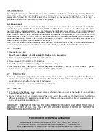
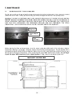
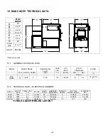
10. MAX CADDY TECHNICAL DATA
MAX
CADDY
"G"
"A"
"D"
"E"
"B"
"C"
"F"
A
57”
B
29 ¾”
C
48 ¾”
D
18 X 20”
E
32 ¼”
F
25 ½”
G
45”
FLUE
PIPE
6” or 7”*
WEIGHT
650 lbs
* Reducer required
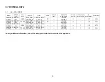
10.1 GENERAL
TECHNICAL
DATA
MODEL DIRECT
DRIVE
THEORETICAL
FLOW
TEMP
VAR.
BTU
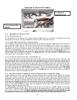
INPUT
STATIC
PRESSURE
FILTER
FAN MOTOR SPEED
(CFM)
(
O
F)
(WOOD)
MIN.
MAX.
(1)
IN.W.C.
MAX
CADDY
G-
10
1/2HP 4
1780
100 180,000 0,2
0,5
16” x 20” X
1”
10.2
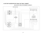
TECHNICAL DATA – ELECTRICAL ELEMENT
MODEL
OUTPUT
(CFM)
TEMP. VAR.
(
O
F)
BTU/HR
AMPS
TOTAL
BREAKER
REQUIRED
FEEDER
GAUGE
VOLTAGE
SINGLE PHASE
ELEMENTS
QTY
20 kW
1800
75
68,240
85
125 amps
3
120/240
4 x 5 kW
25 kW
1800
85
85,325
100
150 amps
2
120/240
5 x 5 kW
WOOD 1800
100
180,000 5
15
amps
14
120
N/A
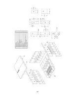
11. MAX CADDY BRICKS LAYOUT
Summary of Contents for MAX CADDY PF01101
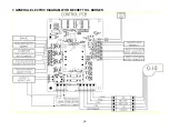
Page 38: ...38 7 GENERAL ELECTRIC DIAGRAM WITH BECKETT OIL BURNER ...
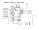
Page 39: ...39 8 GENERAL ELECTRIC DIAGRAM WITH RIELLO OIL BURNER ...
Page 42: ...42 ...
Page 45: ......


