47
3. APPLIANCE INSTALLATION
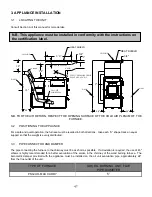
3.1 LOCATING
THE
UNIT
Consult Section A of this manual for more details.
WALL
18''
18''
OIL UNIT
SMOKE PIPE
WALL
9''
HOT AIR PLENUM
CEILLING
6''
6' 0''
STATIC PRESSURE CHECK
POINT MIN. 0.20" W.C.
1"
CEILLING
WALL
24"
3/4"
HEAT SHIELD
24"
24"
3/4"
HEAT SHIELD
45° ELBOW
24''
8'' MIN.
N.B. FOR THE AIR RETURN, RESPECT THE OPENING SURFACE OF THE COLD AIR PLENUM OF THE
FURNACE.
3.2
POSITIONING THE APPLIANCE
For a safe and quiet operation, the furnace must be levelled in both directions. Give each “U” shape track an equal
support so that the weight is evenly distributed.
3.3
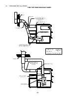
PIPE CONNECTOR AND DAMPER
The pipe connecting the furnace to the chimney must be as short as possible. If a deviation is required, the use of 45
o
elbows is highly recommended for a better evacuation of the smoke in the chimney of the wood burning furnace. The
barometric damper provided with the appliance must be installed on the oil unit evacuation pipe, approximately 24
"
from the flue outlet of the unit.
TYPE OF FURNACE
(UH) OIL BURNING UNIT FLUE
PIPE DIAMETER
PSG/ UH-MAX CADDY
5”
N.B. This appliance must be installed in conformity with the instructions on
the certification label.
Summary of Contents for MAX CADDY PF01101
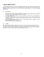
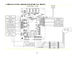
Page 38: ...38 7 GENERAL ELECTRIC DIAGRAM WITH BECKETT OIL BURNER ...
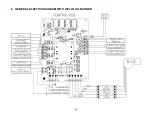
Page 39: ...39 8 GENERAL ELECTRIC DIAGRAM WITH RIELLO OIL BURNER ...
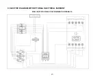
Page 42: ...42 ...
Page 45: ......

