49
3.5 COMBUSTION
AIR
Consult Section A of this manual for more details.
3.6 ELECTRICAL
WIRING
The whole wiring from the distribution panel to the heating unit shall comply with the applicable electrical standards and
local codes. The unit should be connected to its own 15 amp/120VAC electric circuit. Consult section A of this manual
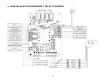
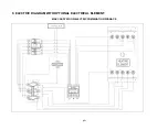
for the electrical wiring diagram using a Beckett or Riello burner.
3.7 THERMOSTAT
Both the wood and oil thermostats must be installed side by side on an interior wall, in a location where they are not
affected by the air draft coming from the furnace’s blower; they must be level and at least 55 inches above the floor.
Consult section A of this manual for more details regarding the thermostats.
3.8 FAN
CONTROL
In the case of the oil option, the blower starts once the request for heat is activated by the oil option’s thermostat.
The adjustment of all controls must be performed by a qualified technician. For continuous operation of the blower
during Summer, the mode must be changed to CIRC on the PC board. Then, the appropriate blower speed must be
selected.
It is not recommended to let the blower run on continuous mode when heating with wood since the wood
furnace must reach a certain temperature before the blower starts in order to operate efficiently.
3.9
COMBUSTION SAFETY CONTROL
The AFG type oil burner is equipped with an electronic control (# R7184B1032) including a pre-purge function and a
new, more durable drive motor.
PRE-PURGE
When there is a call for heat, the burner’s fan will run for 15 seconds before the actual ignition takes place to vent the
combustion chamber and generate a proper draft. This will result in a smoother ignition of the oil burner.
SAFE OPERATION
If the flame goes out while the burner is running, the CAD cell will detect it; the control will then switch to the
"RECYCLE" mode and cut the fuel supply to the burner for 60 seconds. After this delay, the control goes back to
"IGNITION" mode. If the flame goes out 3 times in a row, the control will switch to the "LOCKOUT" mode to prevent a
continuous cycling of the ignition process, which would cause a premature soot-up of the combustion chamber and
smoke pipe. To deactivate the “LOCKOUT” mode, press and hold the reset button of the control for 30 seconds.
A green diagnostic LED on the control has four states:
-
On = Flame present
-
Off = No flame
-
2 seconds On, 2 seconds Off = "Recycle" mode
-
1/2 second On, 1/2 second Off = "Lockout" mode TEMPORARY SHUT-OFF
By pressing and holding the reset button, the burner will shut-off until the reset button is released. When the button is
released, the control will start over at the beginning of the normal cycle.
FOR ADDITIONAL INFORMATIONS ON OPERATION SEQUENCES OF THE BURNER, CONSULT THE BURNER
INSTRUCTION MANUAL.
3.10
COMBUSTION ADJUSTMENT AND VERIFICATION
To enjoy the efficiency of our oil burning units, you must respect the following criterion:
Oil burning units must be connected to flue pipes having at all times a sufficient draft to ensure an efficient and safe
operation of unit.
Summary of Contents for MAX CADDY PF01101
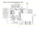
Page 38: ...38 7 GENERAL ELECTRIC DIAGRAM WITH BECKETT OIL BURNER ...
Page 39: ...39 8 GENERAL ELECTRIC DIAGRAM WITH RIELLO OIL BURNER ...
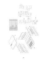
Page 42: ...42 ...
Page 45: ......

