27
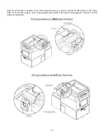
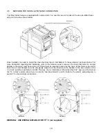
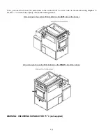
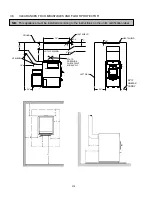
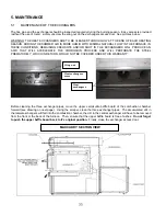
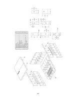
INSIDE VIEW OF THE ELECTRIC ELEMENT
3.13 THERMOSTAT
INSTALLATION
3.13.1 Wood furnace only
The thermostat must be installed on an inside wall and located where it is not likely to be affected by the draft
coming from an air outlet. It must be installed at a minimum of 55 inches above the floor.
3.13.2 Combination wood-electric or wood-oil furnace
The combination model uses two thermostats which must be located at the same height from the floor. When the
main thermostat (wood) calls for heat and the demand cannot be satisfied by the furnace with wood as a
combustible, the option (oil burner or electric unit) will take over and maintain the house at the temperature
programmed on the second thermostat (option). If the thermostats use a dry contact, hook-up the main thermostat
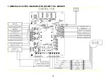
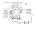
(wood) to the WOOD MECH port on the PC board and the option’s thermostat to the USER MECH port. If the
thermostats send a 24 volt signal to the appliance, hook-up the main thermostat (wood) to the WOOD 24V port on
the PC board and the option’s thermostat to the USER 24V port. For more information regarding the wiring
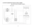
connections, refer to the diagrams in section 7.
3.13.3 Trio furnace (wood-oil-electric or wood-electric-oil )
The trio model also uses two thermostats which must be located at the same height from the floor. When the main
thermostat (wood) calls for heat and the demand cannot be satisfied by the furnace with wood as a combustible, the
first option will take over and maintain the house at the temperature programmed on the second thermostat (option).
Should the first option be unable to satisfy the call for heat, the second option will take over and maintain the house
at the temperature programmed on the second thermostat (option). If the thermostats use a dry contact, hook-up the
main thermostat (wood) to the WOOD MECH port on the PC board and the option’s thermostat to the USER MECH
port. If the thermostats send a 24 volt signal to the appliance, hook-up the main thermostat (wood) to the WOOD
24V port on the PC board and the option’s thermostat to the USER 24V port. For more information regarding the
wiring connections, refer to the diagrams in section 7.
3.14
INSTALLATION OF A DOMESTIC WATER PRE-HEATING SYSTEM (OPTIONAL)
A water heating loop option is also available to pre-heat domestic water using the energy produced by the Max
Caddy wood furnace. This water loop kit will be inserted between the wood combustion chamber and the heat
exchangers. When heating with wood, the heat from the furnace will pre-heat domestic water that will be stored in a
feed tank before entering your existing water heater. Removable panels are installed on both sides of the furnace for
quick and easy installation of the loop. A 24 volt solenoid valve must be installed at the inlet of the loop and must be
connected to the WATR SOLN terminal on the PC board; when the plenum temperature reaches 140°F, the valve
opens to allow water circulation. It closes when the temperature drops below 120°F to prevent overcooling the
combustion chamber during low firing rates.
The WATR SOLN terminal may also be used to activate the 24 volt relay of a humidifier installed in the system
which, when connected to the PC Board, will be activated and deactivated at the same temperatures as the water
solenoid valve (140°F et 120°F).
Complete installation and operation instructions for the hot water loop kit
are supplied with the kit and can be downloaded from the PSG web site at www.psg-distribution.com.
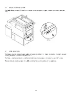
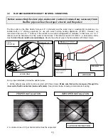
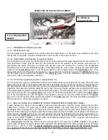
L-170 Thermodisc
RESET
Red button
manual reset
Summary of Contents for MAX CADDY PF01101
Page 38: ...38 7 GENERAL ELECTRIC DIAGRAM WITH BECKETT OIL BURNER ...
Page 39: ...39 8 GENERAL ELECTRIC DIAGRAM WITH RIELLO OIL BURNER ...
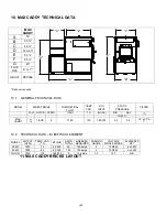
Page 42: ...42 ...
Page 45: ......

