background image

Service Facts

© 2011  Trane     All Rights Reserved

NOTICE: The manufacturer has a policy of continuous product and product data improvement and reserves the right to change design and specifications without notice.

PRODUCT SPECIFICATIONS 

1

MODEL
TYPE
RATINGS   

2

1st Stage Input BTUH

1st Stage Capacity BTUH (ICS)  

3

2nd Stage Input BTUH

2nd Stage Capacity BTUH (ICS) 


3

AFUE
Temp. rise (Min.-Max.) °F.

BLOWER DRIVE

Diameter - Width (In.)
No. Used
Speeds (No.)
CFM vs. in. w.g.
Motor HP
R.P.M.
Volts / Ph / Hz

COMBUSTION FAN - Type

Drive -  No. Speeds
Motor HP - RPM
Volts / Ph / Hz
FLA

FILTER — Furnished?

Type Recommended
Hi Vel. (No.-Size-Thk.)

VENT — Size (in.)
HEAT EXCHANGER

Type -Fired

-Unfired

Gauge (Fired)

ORIFICES — Main

Nat. Gas. Qty. — Drill Size
L.P. Gas Qty. — Drill Size

GAS VALVE
PILOT SAFETY DEVICE

Type

BURNERS — Type

Number

POWER CONN. — V / Ph / Hz  

4

Ampacity (In Amps)
Max. Overcurrent Protection (Amps)

PIPE CONN. SIZE (IN.)
DIMENSIONS

Crated (In.)

WEIGHT

Shipping (Lbs.) / Net (Lbs)

*UH2B080A9V3VA

Upflow / Horizontal

52,000
50.440
80,000
77,600

97

35 - 65

DIRECT

10 x 8

1

Variable

See Fan Performance Table

1/2

Variable

115/1/60

Centrifugal

Direct - Variable

1/50 - 5000

33 - 110/3/60 - 180

1.0

Yes

High Velocity

1 - 17x25 - 1 in.

2 Round

Aluminized Steel - Type I

20

4 — 45
4 — 56

Redundant - Two Stage

Hot Surface Igniter

Multiport Inshot

4

115/1/60

11.1

15

1/2

H x W x D

41-3/4 x 19-1/2 x 30-1/2

168 / 156

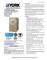
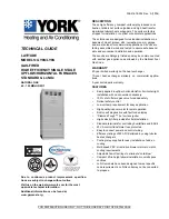
Gas Furnace – Var. Speed Blower –
Var. Speed Inducer – Two Stage Heat –
Direct Vent

Models:

* - First letter may be “A” or “T”

IMPORTANT — This document contains a wiring diagram and service information. This is customer property and is to

remain with this unit. Please return to service information pack upon completion of work.

DISCONNECT POWER BEFORE SERVICING

WARNING

*UH2B060A9V3VA

Upflow / Horizontal

39,000
37,830
60,000
58,200

97

35 - 65

DIRECT

10 x 8

1

Variable

See Fan Performance Table

1/2

Variable

115/1/60

Centrifugal

Direct - Variable

1/50 - 5000

33 - 110/3/60 - 180

1.0

Yes

High Velocity

1 - 17x25 - 1 in.

2 Round

Aluminized Steel - Type I

20

3 — 45
3 — 56

Redundant - Two Stage

Hot Surface Igniter

Multiport Inshot

3

115/1/60

11.1

15

1/2

H x W x D

41-3/4 x 19-1/2 x 30-1/2

158 / 146

*UH2C100A9V4VA

Upflow / Horizontal

65,000
62,855

100,000

96,700

97

35 - 65

DIRECT

10 x 10

1

Variable

See Fan Performance Table

3/4

Variable

115/1/60

Centrifugal

Direct - Variable

1/50 - 5000

33 - 110/3/60 - 180

1.0

Yes

High Velocity

1 - 20x25 - 1 in.

3 Round

Aluminized Steel - Type I

20

5 — 45
5 — 56

Redundant - Two Stage

Hot Surface Igniter

Multiport Inshot

5

115/1/60

13.5

20

1/2

H x W x D

41-3/4 x 23 x 30-1/2

197 / 185

1

Central Furnace heating designs are certified to ANSI Z21.47 / CSA 2.3.

2

For U.S. applications, above input ratings (BTUH) are up to 2,000 feet, derate 4% per 1,000 feet for elevations above 2,000 feet above sea level.
For Canadian applications, above input ratings (BTUH) are up to 4,500 feet, derate 4% per 1,000 feet for elevations above 4,500 feet above sea level.

3

Based on U.S. government standard tests.

4

The above wiring specifications are in accordance with National Electrical Code; however, installations must comply with local codes.

AVAILABLE IN FRENCH CANADIAN (FC)

UH2-SF-1G

X3 4 3 0 7 0 P0 8

*UH2B060A9V3VA
*UH2B080A9V3VA
*UH2B080A9V4VA
*UH2C100A9V4VA

*UH2C100A9V5VA
*UH2D120A9V5VA
*DH2B060A9V3VA
*DH2B080A9V3VA

*DH2B080A9V4VA
*DH2C100A9V4VA
*DH2D120A9V5VA

*UH2B080A9V4VA

Upflow / Horizontal

52,000
50,440
80,000
77,600

97

35 - 65

DIRECT

11 x 8

1

Variable

See Fan Performance Table

3/4

Variable

115/1/60

Centrifugal

Direct - Variable

1/50 - 5000

33 - 110/3/60 - 180

1.0

Yes

High Velocity

1 - 17x25 - 1 in.

2 Round

Aluminized Steel - Type I

20

4 — 45
4 — 56

Redundant - Two Stage

Hot Surface Igniter

Multiport Inshot

4

115/1/60

13.5

20

1/2

H x W x D

41-3/4 x 19-1/2 x 30-1/2

170 / 158

Summary of Contents for *DH2B060A9V3VA

Page 1: ...7 830 60 000 58 200 97 35 65 DIRECT 10 x 8 1 Variable See FanPerformance Table 1 2 Variable 115 1 60 Centrifugal Direct Variable 1 50 5000 33 110 3 60 180 1 0 Yes High Velocity 1 17x25 1 in 2 Round Aluminized Steel Type I 20 3 45 3 56 Redundant Two Stage Hot Surface Igniter Multiport Inshot 3 115 1 60 11 1 15 1 2 HxWxD 41 3 4 x 19 1 2 x 30 1 2 158 146 UH2C100A9V4VA Upflow Horizontal 65 000 62 855 ...

Page 2: ...D120A9V5VA Upflow Horizontal 78 000 75 426 120 000 116 040 96 7 40 70 DIRECT 10 x 10 1 Variable See FanPerformance Table 1 Variable 115 1 60 Centrifugal Direct Variable 1 50 5000 33 110 3 60 180 1 0 Yes High Velocity 1 24x25 1 in 3 Round Aluminized Steel Type I 20 6 45 6 56 Redundant Two Stage Hot Surface Igniter Multiport Inshot 6 115 1 60 15 2 20 1 2 HxWxD 41 3 4 x 26 1 2 x 30 1 2 206 193 1 Cent...

Page 3: ... 0 Yes High Velocity 2 16x20 1 in 3 Round Aluminized Steel Type I 20 6 45 6 56 Redundant Two Stage Hot Surface Igniter Multiport Inshot 6 115 1 60 15 2 20 1 2 HxWxD 41 3 4 x 26 1 2 x 30 1 2 206 196 DH2C100A9V4VA Downflow Horizontal 65 000 61 750 100 000 95 000 95 35 65 DIRECT 10 x 10 1 Variable See FanPerformance Table 3 4 Variable 115 1 60 Centrifugal Direct Variable 1 50 5000 33 110 3 60 180 1 0...

Page 4: ...tions of use WARNING SAFETY SECTION WARNING ELECTRIC SHOCK HAZARD THE CABINET MUST HAVE AN UNINTERRUPTED OR UNBROKEN GROUND ACCORDING TO NATIONAL ELEC TRICAL CODE ANSI NFPA 70 LATEST EDITION AND CANADIAN ELECTRICAL CODE CSA C22 1 OR LOCAL CODES TO MINIMIZE PERSONAL INJURY IF AN ELECTRI CAL FAULT SHOULD OCCUR FAILURE TO FOLLOW THIS WARNING COULD RESULT IN AN ELECTRICAL SHOCK FIRE INJURY OR DEATH WA...

Page 5: ...lush eyes with water to remove dust If symptoms persist seek medical attention Skin Contact Wash affected areas gently with soap and warm water after handling SEQUENCE OF OPERATION COMFORT CONTROL CALL FOR HEAT 2 STAGE COMFORT CONTROL Call for 1st Stage only W1 Comfort Control contacts close signaling the control module to run its self check routine After the control module has verified that the 1...

Page 6: ...motor is reduced to low speed 1st stage satisfied W1 Comfort Control contacts open signaling that 1st Stage heating requirements are satisfied The Gas Valve will close and the induced draft blower will be de energized The indoor blower motor will continue to run for the fan off period Field selectable at 60 100 140 or 180 seconds then will be de energized by the control module Comfort Control call...

Page 7: ...xtremely hot 4 IGNITER This unit has a hot surface direct ignition device that automatically lights the burners Please note that it is very fragile and should be handled with care 5 BURNER Gas burners do not normally require sched uled servicing however accumulation of foreign material may cause a yellowing flame or delayed ignition Either condition indicates that a service call is required For be...

Page 8: ...8 Service Facts X343070P08 UH2 WIRING DIAGRAM From drawing D344303 ...

Page 9: ...9 Service Facts X343070P08 UH2 SCHEMATIC DIAGRAM2 From drawing D344303 ...

Page 10: ...10 Service Facts X343070P08 DH2 WIRING DIAGRAM From drawing D344304 ...

Page 11: ...11 Service Facts X343070P08 DH2 SCHEMATIC DIAGRAM From drawing D344304 ...

Page 12: ...otor Will N ot Run ECM 2 TM QUICK CHECK Blower Motor Will Not Run 1 Jumper 24 V olt A C R T erminal to G terminal on the Low Voltage Terminal board Does motor run NO Go to step 2 YES Motor runs check Comfort Control and Comfort Control wire 2 Unplug 16 wire low voltage harness from the interface board Jumper 24 V olts A C to pins 12 15 and common pins 1 and 3 Does the motor run NO Go to step 3 YES...

Page 13: ... C to motor low voltage plug pins 12 and 15 and pins 1 and 3 which are common Does motor run NO Go to step 4 YES Fault is in the 16 wire low voltage harness Repair or replace it 4 I s the line voltage to the motor high voltage power plug pin 4 and pin 5 correct NO Correct line voltage fault YES Live voltage correct and motor will not run Replace motor TO PIN 1 3 24 VOLT A C ...

Page 14: ...D on the board should be on 6 If the troubleshooter R L E D is not on check for 24 volts A C at the motor control board 7 If 24 volts A C is not present troubleshoot and repair as needed 8 If 24 volts A C is present check the trouble shooter R L E D and check continuity of the 16 wire cable pin 1 to pin 1 through pin 16 If troubleshooter R L E D is good and 16 wire cable pin 1 and pin 12 are good ...

Page 15: ...is bad repair or re place Low Voltage Comfort Control Operation 14 Verify thermostat signals by jumping R to each of the low voltage terminal connections as follows BK O YLO G W1 W2 W3 See exceptions below for furnaces and retro fit motor control boards The corre sponding L E D on the troubleshooter should light when R is applied Verify L E D s on the motor control board light according to the app...

Page 16: ...FF CFM WATTS 1325 360 1325 425 1300 460 1175 425 1000 365 NOTES First letter may be A or T 1 At continuous fan setting Heating or Cooling airflows are approximately 50 of selected cooling value 2 LOW airflow 350 cfm ton is COMFORT HUMID CLIMATE setting NORMAL airflow 400 cfm ton is typical setting HIGH airflow 450 cfm ton is DRY CLIMATE setting UH2B060A9V3V FURNACE HEATING AIRFLOW CFM AND POWER WA...

Page 17: ...OW SETTING DIP SWITCH SETTING EXTERNAL STATIC PRESSURE SW 1 SW 2 SW 3 SW 4 0 1 0 3 0 5 0 7 0 9 2 0 LOW 350 CFM TON ON ON OFF ON CFM WATTS 750 84 750 122 750 154 720 185 710 221 NORMAL 400 CFM TON ON ON OFF OFF CFM WATTS 840 109 840 146 840 181 840 226 820 264 HIGH 450 CFM TON ON ON ON OFF CFM WATTS 940 136 940 177 940 215 940 274 940 318 2 5 LOW 350 CFM TON OFF ON OFF ON CFM WATTS 850 113 850 150 ...

Page 18: ...TING DIP SWITCH SETTING EXTERNAL STATIC PRESSURE SW 1 SW 2 SW 3 SW 4 0 1 0 3 0 5 0 7 0 9 2 5 LOW 350 CFM TON ON ON OFF ON CFM WATTS 857 107 849 143 841 179 833 223 825 266 NORMAL 400 CFM TON ON ON OFF OFF CFM WATTS 970 158 971 205 973 251 966 298 960 345 HIGH 450 CFM TON ON ON ON OFF CFM WATTS 1082 209 1093 266 1104 323 1099 374 1095 424 3 0 LOW 350 CFM TON OFF ON OFF ON CFM WATTS 1004 153 1019 21...

Page 19: ...OFF OFF ON OFF CFM WATTS 1847 630 1863 735 1816 780 1687 720 1532 665 NOTES First letter may be A or T 1 At Continuous fan setting Heating or Cooling airflows are approximately 50 of selected cooling value 2 LOW airflow 350 cfm ton is COMFORT HUMID CLIMATE setting NORMAL airflow 400 cfm ton is typical setting HIGH airflow 450 cfm ton is DRY CLIMATE setting UH2C100A9V4V FURNACE HEATING AIRFLOW CFM ...

Page 20: ...0A9V5V FURNACE COOLING AIRFLOW CFM AND POWER WATTS VS EXTERNAL STATIC PRESSURE WITH FILTER OUTDOOR UNIT SIZE TONS AIRFLOW SETTING DIP SWITCH SETTING EXTERNAL STATIC PRESSURE SW 1 SW 2 SW 3 SW 4 0 1 0 3 0 5 0 7 0 9 3 5 LOW 350 CFM TON OFF ON OFF ON CFM WATTS 1163 222 1201 304 1209 375 1200 433 1199 495 NORMAL 400 CFM TON OFF ON OFF OFF CFM WATTS 1339 331 1365 400 1366 477 1377 555 1382 636 HIGH 450...

Page 21: ...Heating or Cooling airflows are approximately 50 of selected cooling value 2 LOW airflow 350 cfm ton is COMFORT HUMID CLIMATE setting NORMAL airflow 400 cfm ton is typical setting HIGH airflow 450 cfm ton is DRY CLIMATE setting UH2D120A9V5V FURNACE HEATING AIRFLOW CFM AND POWER WATTS VS EXTERNAL STATIC PRESSURE WITH FILTER 1st Stage Capacity 2nd Stage Capacity 75 426 116 040 AIRFLOW SETTING DIP SW...

Page 22: ...FLOW SETTING DIP SWITCH SETTING EXTERNAL STATIC PRESSURE SW 1 SW 2 SW 3 SW 4 0 1 0 3 0 5 0 7 0 9 1 5 LOW 350 CFM TON OFF OFF OFF ON CFM WATTS 525 45 525 70 525 100 525 135 525 160 NORMAL 400 CFM TON OFF OFF OFF OFF CFM WATTS 600 55 600 85 600 120 600 150 600 185 HIGH 450 CFM TON OFF OFF ON OFF CFM WATTS 675 65 675 105 625 140 675 175 675 205 2 0 LOW 350 CFM TON ON ON OFF ON CFM WATTS 700 70 700 11...

Page 23: ...ooling airflows are approximately 50 of selected cooling value 2 LOW airflow 350 cfm ton is COMFORT HUMID CLIMATE setting NORMAL airflow 400 cfm ton is typical setting HIGH airflow 450 cfm ton is DRY CLIMATE setting DH2B080A9V3V FURNACE HEATING AIRFLOW CFM AND POWER WATTS VS EXTERNAL STATIC PRESSURE WITH FILTER 1st STAGE CAPACITY 2nd STAGE CAPACITY 49 400 76 000 AIRFLOW SETTING DIP SWITCH SETTING ...

Page 24: ...W SETTING DIP SWITCH SETTING EXTERNAL STATIC PRESSURE SW 1 SW 2 SW 3 SW 4 0 1 0 3 0 5 0 7 0 9 2 5 LOW 350 CFM TON ON ON OFF ON CFM WATTS 849 141 865 191 881 241 878 294 876 348 NORMAL 400 CFM TON ON ON OFF OFF CFM WATTS 953 195 965 250 977 305 973 358 970 411 HIGH 450 CFM TON ON ON ON OFF CFM WATTS 1057 249 1065 309 1073 369 1069 422 1064 474 3 0 LOW 350 CFM TON OFF ON OFF ON CFM WATTS 999 188 100...

Page 25: ...TONS AIRFLOW SETTING DIP SWITCH SETTING EXTERNAL STATIC PRESSURE SW 1 SW 2 SW 3 SW 4 0 1 0 3 0 5 0 7 0 9 2 5 LOW 350 CFM TON ON ON OFF ON CFM WATTS 870 100 885 140 887 185 881 230 876 270 NORMAL 400 CFM TON ON ON OFF OFF CFM WATTS 989 120 1018 180 1016 230 1012 285 999 325 HIGH 450 CFM TON ON ON ON OFF CFM WATTS 1124 175 1139 225 1130 275 1135 335 1135 390 3 0 LOW 350 CFM TON OFF ON OFF ON CFM WAT...

Page 26: ...g DH2D120A9V5V FURNACE COOLING AIRFLOW CFM AND POWER WATTS VS EXTERNAL STATIC PRESSURE WITH FILTER OUTDOOR UNIT SIZE TONS AIRFLOW SETTING DIP SWITCH SETTING EXTERNAL STATIC PRESSURE SW 1 SW 2 SW 3 SW 4 0 1 0 3 0 5 0 7 0 9 3 5 LOW 350 CFM TON OFF ON OFF ON CFM WATTS 1225 240 1225 280 1225 340 1225 400 1225 450 NORMAL 400 CFM TON OFF ON OFF OFF CFM WATTS 1400 310 1400 390 1400 470 1400 520 1400 570 ...

Page 27: ...3 times within 6 seconds The control will acknowledge the reset by turning on the red LED for 2 seconds FAULT CODE RECOVERY On power up last 4 faults if any will be flashed on the red LED The newest fault detected will flash first and the oldest last There will be a 2 second delay between fault code flashes Solid red LED error codes will not be displayed The Green LED will be on solid during last ...

Page 28: ...when applying an airflow command signal to the BK input such as with the variable speed single zone and multi zone system controller On single speed cooling only non heat pump systems jumper Y to O for proper operation of the delay profiles and the humidistat For two compressor or two speed systems jumper Ylo to O The factory installed jumper between R and BK on the circuit board must be cut if an...

Page 29: ...al Gas Valve Circuit Fault 41 8 Flash Troubleshooting Low Flame Sense Fault 42 9 Flash Troubleshooting Open Inducer Limit 43 VS No Air Flow Incorrect Air Flow The following pages include troubleshooting flowcharts in reference to the 95 Two Stage UH2 furnaces ONLY using the FAULT LED as starting points The information contained is for reference only and does not cover all scenarios or problems tha...

Page 30: ...XFMR N CNT05160 Line Voltage Connections 24 Volt Furnace Component Connections 5 Amp Control Fuse Low Voltage Terminal Strip 16 pin ECM Connector Indoor airflow configuration dip switches Fault LED Red 1 BK 6 2 RD 6 3 WH 6 4 N A 1 2 3 4 W1 W2 Staging Delay Heat Off Delay Integrated Furnace Control IFC Component Layout ...

Page 31: ...ER OR PRESSURE SWITCH ERROR 4 Flashes OPEN LIMIT OR ROLLOUT SWITCH 5 Flashes FLAME SENSED WHEN NO FLAME SHOULD BE PRESENT 6 Flashes LINE REVERSE POLARITY 7 Flashes GAS VALVE CIRCUIT ERROR 8 Flashes WEAK FLAME 9 Flashes OPEN INDUCER LIMIT ERROR GREEN LED STATUS Slow Flash NORMAL NO CALL FOR HEAT Fast Flash NORMAL CALL FOR HEAT PRESENT GREEN and RED LED s on Continuously FUSE OPEN OR INTERNAL CONTRO...

Page 32: ...e present from transformer and fuse good YES NO Repair low voltage wiring replace transformer or fuse as needed Repair high voltage connection to unit What is the fault light flash code See FAULT LED Flash Codes page YES Are connections and wiring in working condition Repair connections NO Close and hold door switch YES GETTING STARTED ...

Page 33: ...heck operation NO Flame sensor is good NO Is minimum outlet gas manifold pressure maintained Does inlet gas pressure drop more than 2 WC NO Correct inlet gas pressure Check operation Replace Gas Valve Check operation YES Disconnect electrical power to furnace Connect manometer to oulet gas pressure connector NO Cycle power to furnace and call for heat YES DEFINITION RETRY Lock Out 3 unsuccessful t...

Page 34: ...34 Service Facts X343070P08 Correct positioning of ignitor sensor NOTE the slight over lap of the ignitor and the burner Igniter slightly overlapping OD of burner ...

Page 35: ...tion YES While the furnace is operating on 1st stage heat make a call for 2nd stage heat Allow 30 seconds for the furnace to transition to 2nd stage Is 24 volts present measured across PS2 yellow 7 to brown See Note 1 Is pressure greater than pressure switch label See Note 2 NO Replace pressure switch Check operation Cycle power to the furnace and call for 1st stage heat NO YES NO Replace or repai...

Page 36: ...Correct gas pressure Check operation NO Is temperature at high limit above the switch setting YES Replace high limit switch NO YES Is temperature at reverse flow switch above specifications Replace reverse flow switch NO Check for excessive reverse flow during an off cycle YES DEFINITION Limit switches are safety devices that will open when an abnormal high temperature has been sensed REMOVE ALL J...

Page 37: ...O Is flue piping restricted Correct as needed Check operation YES Are flames from burners impinging on sides of heat exchanger NO YES When fan comes on do flames stay consistent Replace heat exchanger Check operation NO Replace Roll out switch Check operation YES DEFINITION Limit switches are safety devices that will open when an abnormal high temperature has been sensed REMOVE ALL JUMPER WIRING T...

Page 38: ...ping per installation instructions Using a back up wrench install new gas valve Check operation Inspect gas supply for leaks and have gas supplier check gas quality Are there signs of moisture or debris in the inlet gas screen YES Install drip leg per National Fuel Gas Code and Installation Instructions YES NO NO Turn off gas supply Remove gas valve 5 Flash Fault LED ...

Page 39: ...343070P08 DEFINITION Polarity Fault Incoming high voltage wiring is reversed Disconnect incoming electrical power to furnace Reverse 120 vac power leads to furnace wiring Reconnect power Check operation 6 Flash Fault LED ...

Page 40: ...ircuit Error 24 volts is present when it should not be present Is 24 VAC nominal voltage present between Red lead at gas valve connection to chassis ground Turn Comfort Control to OFF position Correct wiring Check operation YES Replace IFC NO 7 Flash Fault LED ...

Page 41: ...41 Service Facts X343070P08 ...

Page 42: ...pen Replace Inducer Limit switch Check operation YES NO Definition This error is normally caused by improper installation or application of the furnace venting system Disconnect electrical power from the furnace and remove 1 wire from the limit switch Is continuity measured across inducer limit switch Verify venting and vent terminations are within allowable limits and clear any obstructions Induc...

Page 43: ...or run YES Replace Wire harness NO Is 24 VAC measured between R transformer hot and B C transformer common at the low voltage field connections NO Replace transformer NO Repair wiring between incoming power supply and transformer Is fuse blown YES Replace fuse NO Is the proper line voltage present at the transformer YES YES Remove motor module and ohm motor windings Are motor windings ok See Note ...

Page 44: ...has a policy of continuous product and product data improvement and reserves the right to change design and specifications without notice Trane 6200TroupHighway Tyler TX75707 Formoreinformationcontact your local dealer ...

Reviews: