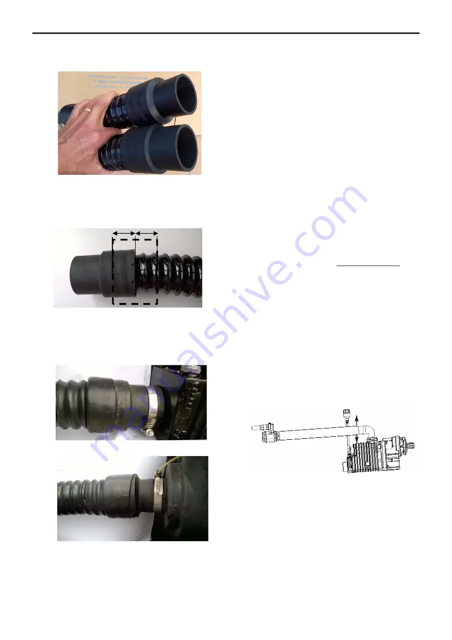
• Result :
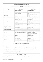
• To pass a heat-shrinkable sleeve on an end and to
center it on the end of the hump. To retract gradually by
means of a heat gun. Attention not to point the gun
towards the hose not covered, risk of perforation.
To proceed in the same way at the other end.
• To check the hose is perfectly clean inside, and to remove
the protections caps on the compressor.
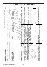
• To assemble the unit on the compressor inlet port and
to tighten the clamp : cast solid end.
Example :
• To proceed in the same way with the air filter.
• To then suspend the hose while taking care to protect
it from any friction and the potentially hot bodies such
as muffler.
The inlet filter should be positioned to draw in clean, cool
air, and should be mounted away from any engine heat
and exhaust.
The compressor inlet suction air must be filtered in order
to eliminate particles bigger than 5 µm.
The maximum pressure drop at suction must be lower
than 75 mbar.
A restriction indicator system must permit changing the
suction filter when it creates a pressure drop greater
than 75 mbar.
The maximum acceptable temperature at suction as a
function of equipment operating conditions is given in
the § TECHNICAL CHARACTERISTICS.
3.4.2 Outlet
The flange supplied must be equipped with its gasket,
screw tightened at 44 Nm.
Piping MUST be at least as large as the compressor
suction and discharge connections.
All the connections located between the compressor and
the trailer hose connection point must be absolutely
waterproof. For that reason, they must be welded.
The B200 PF compressors directly flanged onto the
power take-off must be fitted with the metallic discharge
hose delivered with the equipment. This woven stainless
steel hose is designed to avoid having any stresses
applied on the compressor flange and the rigid pipes of
the systems, as induced by the relative movements of
the compressor with respect to the chassis.
For the B200 PF, it should cancel the stresses on the
flange, as induced by the movement of the compressor,
and respect the rules below :
• install a 90° elbow between the flange and the hose.
• support the stainless steel hose correctly at its end part.
• the hose output pins should be mounted in the same
horizontal plane. Make sure that the installation allows
a compressor displacement of ± 5 cm to be obtained.
• on the same horizontal plane, if the output pins are
not parallel, the bending radius must be as large as
possible, and in any case at least equal to 50 cm.
Make sure that the installation allows a compressor
displacement of ± 5 cm to be obtained.
=
=
5 cm
5 cm
15/22
NT 1401-X00 10 18 B200 Flow Control e
3. INSTALLATION (continued)


