13
S-PARK
- rev.1.1_06_2020
3.8
Legenda of terminals
3.8.1
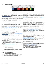
START – wired command contacts
(key switch, key pad, timer)
Any start command contact shall be wired on this terminal, refer to
Any pulse below 10 seconds is considered a regular START command,
including automatic closing mode (L.1 automatic closing); any pul-
se over 10 seconds activates the timer mode and the barrier will
remain in opening position according to the timer settings.
Wire N.O. contacts between START (or START2) and COM.
Any additional contact shall be wired in parallel.
3.8.2
STOP – emergency push button or similar devices
Any stop command contact shall be wired on this terminal.
Multiple stop contacts shall be wired in series.
Wire N.C. contacts between STOP and COM.
If N.C. contact opens the barrier stops. If no STOP contact is wired,
deactivate
parameter P. 1 STOP contact set up
p. 18, otherwise
no operation will start.
Any single STOP pulse immediately stops the operation.
3.8.3
STRT2 (START2: pedestrian opening)
The operation logic is the same of START.
Just set the pedestrian automatic closing,
In case of mirror barriers installation (TWINNING set up), STRT2 will
open just the master barrier.
3.8.4
PH – Closing photocell (N.C. dry contact)
Any closing photocell and similar devices shall be wired on this
terminal, N.C. contacts.
Wire the receiver’s N.C. contact between PH and GND.
Additional photocells shall be wired in series.
Power the receiver on +24 (and GND), while the transmitter on +TX
(and GND).
Refer to
wiring view.
3.8.5
+24 (SAFETY)
Closing photocell (power)
This terminal permanently powers at 24Vdc, 0,5A all safety devices.
On the contrary, +TX terminal cuts power during photocell test.
3.8.6
+TX - Closing photocell
(cuts power during photocell test)
This terminal powers at 24Vdc, – 0,3A all safety devices, but unlike
+24 (SAFETY) cuts the power during photocell test.
3.8.7
LD (Loop Detector)
This terminal can manage both N.O. and N.C. contacts; loop detector
works as closing photocells do, but in addition can also command
an opening start pulse.
Wire the loop detector between LD and GND, and activate
p. 19 choosing the desired function and contact.
3.8.8
+24, R, G and B (BOOM)
LED signalling strip
Wire the LED strip to BOOM terminal, according to colors: black
wire to +24, red wire to R, yellow wire to G and white wire to B.
The LED strip lights up showing the different operation modes;
parameter
P.4 LED strip configuration p. 19,
allows to set up the
signalling mode.
This configuration has to be set when boom is in closing position.
+24Vdc, 0,5A voltage is permanent on te24.
It is possible to keep the boom lit during night: fit a light sensor, N.O.
dry contact and wire it in series to +24 terminal (BOOM).
Then activate
parameter P.5 light sensor mode
It is possible as well to wire the light sensor’s contact between
START2 and COM, or between LD and GND; in this case LD and
START2 loose their initial function.
3.8.9
DAT and GND (TWINNING)
These terminals are used to activate the TWINNING function in
case of a mirror barrier installation.
Wire DAT to DAT and GND to GND of both barriers, then set up
parameter H.6 Master/Slave mode
p. 18.
If the distance between the two barriers is more than 14m, use a
screened cable: shield to GND and core to DAT.
3.8.10 AUX – Relay output
This terminal AUX allows the connection of a relay (N.O. contact)
that can feature several functions.
Refer to
Contacts can max. bear 250V ac/dc, 10 A.
It’s a dry contact, therefore it cannot power direct any device.
Use an external power supply, or in alte24V from +24
SAFETY terminal able to power up to 300 mA.


